4 Materials and Power: Structural Choices and LiPo Battery Management
Two components of a drone are consumed by the act of flying it. The airframe is consumed in crashes — every development program breaks arms, cracks plates, and strips mounts, and the rate at which it does so is a design parameter, not an embarrassment. The battery is consumed by chemistry — every charge cycle, every deep discharge, and every week spent sitting on a shelf at the wrong state of charge takes an irreversible bite out of its capacity. Both consumables are routinely mismanaged for the same reason: the practical rules (“carbon fiber is stiff but shatters,” “store LiPos at half charge”) circulate widely, while the physics that generates the rules does not, so the rules get applied mechanically and fail exactly at the edge cases the physics would have caught.
This chapter supplies the physics behind both sets of rules. The first half takes the material comparison sketched at the end of the Anatomy of a Multirotor chapter — plastic, aluminium, carbon fiber, arranged in a suspiciously tidy table of trade-offs — and develops it quantitatively: what specific stiffness and specific strength actually are, why a laminate fails differently from a printed part, and how to decide, with arithmetic rather than folklore, when a frame component should be carbon and when it should come off a 3D printer. The second half opens up the lithium-polymer cell itself: what sets its voltage, what is physically happening inside a cell stored full or stored empty, and why the storage-charge window of 3.80 to 3.85 V per cell is not a superstition but a chemically motivated optimum with margin you can compute.
4.1 Learning Objectives
- Compare carbon-fiber composite and 3D-printed thermoplastics (PLA, ABS, nylon) as airframe materials using specific stiffness and specific strength, and compute the mass penalty of matching a carbon part’s bending stiffness in printed plastic.
- Describe the dominant failure mode of each material class — brittle fracture and delamination for carbon laminate, layer separation for printed parts — and derive the print-orientation and design rules that follow.
- Explain, at the level of electrode potentials and side reactions, why a LiPo cell degrades when stored fully charged (electrolyte oxidation, gas generation, swelling) and why it is destroyed by over-discharge (copper current-collector dissolution and subsequent internal shorting).
- Specify a correct storage-charge range in volts per cell and state of charge, and justify it quantitatively from calendar-ageing data and self-discharge arithmetic.
- Use internal resistance as a battery health metric: measure it from voltage sag under a known load, and compute the heating and usable-voltage consequences of its growth as a pack ages.
4.2 Key Vocabulary
- Strength-to-weight ratio (specific strength) — a material’s failure stress divided by its density, in kJ/kg when stress is in MPa and density in g/cm³. It ranks materials for structures whose mass budget, not whose volume, is the binding constraint — which is every airborne structure.
- Specific stiffness — elastic modulus divided by density, in MJ/kg. For aircraft structure it usually matters more than specific strength, because frames fail their mission by flexing (vibration, resonance, sensor corruption) long before they fail by breaking.
- Layer separation (delamination) — the characteristic failure mode of fused-filament 3D-printed parts, in which the part splits along the weld planes between deposited layers. Interlayer welds are diffusion bonds formed in the seconds before the plastic cools, and typically reach only 30–70 % of the bulk material’s strength.
- LiPo (Lithium Polymer battery) — a lithium-ion cell built as a laminated foil pouch with a gel-polymer electrolyte, rather than as a rigid metal cylinder. The pouch format saves case mass and permits very high discharge currents, at the price of no mechanical protection: a LiPo that generates internal gas visibly swells.
- Cell voltage — the potential difference between a cell’s cathode and anode, itself a function of state of charge: 4.20 V fully charged, 3.7 V nominal, roughly 3.5 V at the practical in-flight floor, and 3.0 V at the damage threshold below which over-discharge chemistry begins.
- State of charge (SoC) — the fraction of a cell’s rated capacity currently stored, inferred in practice from resting voltage via the cell’s discharge curve.
- Storage charge — the state of charge at which a LiPo should be kept when not in use for more than a few days: roughly 50–60 % of capacity, corresponding to about 3.80–3.85 V per cell.
- Internal resistance — the effective series resistance of a cell, typically a few milliohms when new. It sets the voltage sag under load and the internal heating rate, rises irreversibly as the cell ages, and is the single most useful measurable indicator of pack health.
- C rating — a battery’s rated continuous discharge current expressed as a multiple of its capacity: a 5.2 Ah pack rated 50C may deliver \(50 \times 5.2 = 260\) A continuously. Physically it is a claim about internal resistance and heat rejection, not a separate property.
- Thermal runaway — the self-accelerating failure of a lithium cell in which internal heating drives exothermic decomposition reactions that generate more heat, culminating in venting or fire. It is the hazard that dictates fireproof charging and storage containers.
4.3 The Materials Problem
4.3.1 What the frame is being asked to do
The Anatomy of a Multirotor chapter established the frame’s three jobs — carry the rotor loads into the vehicle’s mass, hold the propeller discs in fixed relative geometry, and keep the airframe’s structural resonances away from the propellers’ 90 Hz and 180 Hz excitation bands so the inertial sensors report vehicle motion rather than frame flex. All three jobs are stiffness jobs before they are strength jobs. A frame that is strong enough not to break but too compliant to hold its geometry produces oscillating attitude estimates, hot motors, and unexplained short flights; a frame that is stiff enough rarely turns out to be the one that breaks in normal flight. Breakage happens in crashes, which is a separate design case with its own logic.
That framing dictates the two figures of merit. For a component whose mass is contested — and on an aircraft every gram is contested, at the exchange rate the payload-endurance calculation in the previous chapter established — materials are compared per kilogram, not per cubic centimetre. Specific stiffness \(E/\rho\) governs the flying structure; specific strength \(\sigma/\rho\) governs crash survival and highly loaded fittings.
The numbers for the materials actually used in small drones:
| Material | Density (g/cm³) | Modulus \(E\) (GPa) | Tensile strength (MPa) | \(E/\rho\) (MJ/kg) | \(\sigma/\rho\) (kJ/kg) |
|---|---|---|---|---|---|
| Carbon laminate, unidirectional (along fibers) | 1.6 | ~135 | ~1500 | ~84 | ~940 |
| Carbon laminate, quasi-isotropic | 1.6 | ~50 | ~550 | ~31 | ~340 |
| Aluminium 6061-T6 | 2.70 | 69 | 276 (yield) | 26 | 102 |
| Nylon (printed, PA12) | 1.01 | ~1.7 | ~50 | ~1.7 | ~50 |
| PLA (printed, in layer plane) | 1.24 | ~3.5 | ~55 | ~2.8 | ~44 |
| ABS (printed, in layer plane) | 1.04 | ~2.2 | ~40 | ~2.1 | ~38 |
Representative handbook and filament-datasheet values; printed-material figures assume a well-tuned printer and loading within the layer plane. Across the layers, printed strength falls to 30–70 % of these figures — a point developed below, because it is the single most important fact about printed structure.
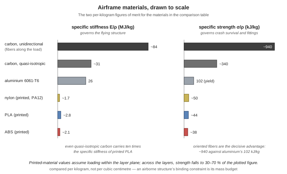
Two readings of the table matter, and Figure 4.1 draws both of them to scale. First, the gap between carbon and the printed thermoplastics is not an increment but an order of magnitude: even the pessimistic quasi-isotropic laminate carries ten times the specific stiffness of PLA. Second, aluminium sits close to quasi-isotropic carbon in specific stiffness — the composite’s decisive advantage appears only when the layup is oriented to put fibers along the load, which is exactly what a frame arm (a cantilever in bending, fibers along its length) allows. This is why carbon dominates drone frames rather than aluminium: not because aluminium is bad, but because a tube or plate loaded in a known direction lets the designer spend the fibers where the stress is.
4.3.2 What the stiffness gap costs in practice
The gap can be converted into mass. Suppose a frame arm must reach a given bending stiffness \(EI\) — the product that sets both its deflection under thrust and its resonant frequency. For a solid rectangular section of fixed width, \(I \propto t^3\), so matching a carbon plate’s \(EI\) in PLA requires a thickness ratio of
\[\frac{t_{\text{PLA}}}{t_{\text{CF}}} = \left(\frac{E_{\text{CF}}}{E_{\text{PLA}}}\right)^{1/3} = \left(\frac{50}{3.5}\right)^{1/3} = 2.4,\]
and the mass ratio is that thickness ratio times the density ratio: \(2.4 \times (1.24/1.6) = 1.9\). An equally stiff printed arm is roughly twice the mass — and since hover power scales as mass to the three-halves, the aircraft pays for that in flight time forever. Alternatively, print the arm at the same geometry and accept the stiffness loss: a cantilever’s first resonant frequency scales as \(\sqrt{E/\rho}\) at fixed geometry, so the printed arm’s first mode falls by a factor of \(\sqrt{31/2.8} \approx 3.3\) — typically from comfortably above the blade-passing excitation to squarely inside the band the propellers excite. Neither option is free; that is why flying primary structure is carbon on essentially every serious airframe.
4.3.3 How each material fails
Carbon laminate fails by fracture and delamination, without warning. A carbon-epoxy laminate is elastic to failure: it reaches perhaps 1–1.5 % strain and then breaks, releasing all the stored energy at once. There is no yield, no bend, no visible warning. In a crash this means an arm either survives intact or snaps — the material cannot absorb impact energy by deforming plastically the way a metal or a tough polymer does. Carbon also fails unpleasantly: fracture surfaces are sharp, splinters are genuinely hazardous to handle, and cutting or sanding carbon releases conductive dust that should be kept out of lungs and electronics alike. Damage short of fracture is more insidious. An impact can delaminate the plies — separate the layers internally — leaving a part that looks intact, measures the right dimensions, and has lost a large fraction of its stiffness and strength. A tap test (delaminated regions sound dull rather than ringing) or flex comparison against a known-good part is part of any competent post-crash inspection.
One more property matters on a flying robot: carbon fiber conducts electricity. A carbon plate behaves as a lossy ground plane, and the Anatomy chapter’s warning about antennas follows directly — GNSS, radio-control, and telemetry antennas mounted flush against carbon are detuned and shadowed, which is why receivers ride on standoffs and antenna tubes on real airframes. The conductivity also means a frayed carbon edge can short an exposed pad, and that carbon dust inside an electronics bay is a slow-motion electrical fault.
Printed parts fail by layer separation, and orientation is destiny. A fused-filament part is a stack of extruded beads welded to their neighbours by heat and time. Within a layer, the plastic approaches its bulk strength; between layers, the weld is a partial diffusion bond formed in the few seconds before the interface cools below the glass transition, and it typically reaches only 30–70 % of bulk strength. A printed part is therefore an anisotropic laminate with its weak planes set by whichever orientation it was printed in — and unlike a carbon layup, where the designer orients fibers along the load, a careless print orients the weak planes wherever the slicer found convenient. The design rule is mechanical common sense once the mechanism is visible: orient the part so that tensile and bending stresses lie within the layer planes, never across them, and treat any load path that must cross layers as operating at roughly half strength. Fillet every corner, because layer lines plus a sharp corner is a crack-starter kit.
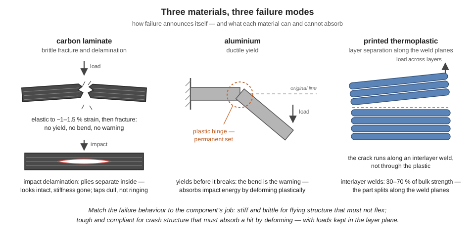
Figure 4.2 puts the three behaviours side by side: the laminate that snaps or delaminates without warning, the metal that bends visibly before it breaks, and the printed part whose weakest planes sit wherever the slicer put them.
The three common filaments then differentiate on toughness and temperature. PLA prints easily and stiffly but is brittle and, critically, has a glass-transition temperature near 60 °C — a black PLA part on a dashboard, in a parked car, or in direct summer sun will warp under no load at all, which disqualifies it from anything structural that lives outdoors. ABS trades printability for a glass transition near 105 °C and much better toughness. Nylon is the least stiff of the three but extraordinarily tough — elongation at break over 100 % — which makes it the choice for parts that must survive impact by deforming: landing-gear feet, camera mounts, propeller guards. Carbon-filled nylon splits the difference, roughly doubling stiffness while keeping useful toughness, and has become the default serious filament for printed drone fittings.
4.3.4 Choosing: a cost model instead of a slogan
The source material frames the decision as premium-durable versus cheap-replaceable, and the frame is right; it just needs numbers attached. For any crash-exposed component, compare the expected cost per incident, not the purchase price. A carbon arm might cost $15 and survive, say, nine out of ten hard landings; a printed arm costs $0.50 in filament and three hours of unattended printer time and might survive half of them. The printed arm is cheaper per crash if the program can tolerate the downtime and the arm’s mass and stiffness penalties — which, per the arithmetic above, flying structure cannot, but brackets, mounts, and guards can. Hence the hybrid rule that every experienced builder converges on and that this book’s build lab applies directly:
- Flying primary structure — arms, centre plates: carbon laminate. Stiffness is the mission.
- Fittings and crash structure — camera mounts, companion-computer trays, landing gear, antenna masts, sensor housings: printed, in ABS or (carbon-)nylon, oriented with the load in the layer plane. Iteration speed is the mission; a bracket that took three hours to print and gets redesigned twice a week is a feature of the development process, not a compromise.
- Threaded and precision interfaces — motor mounts on larger craft, standoffs: aluminium, because machinability and thread strength in a small volume beat both alternatives.
Prototyping deserves the last word: a printed version of a carbon part, flown gently, answers fit and packaging questions in a day for pennies, and the carbon part is then cut once, correctly. The materials are not rivals; they are stages of the same workflow.
4.4 The Power Problem: Living with Lithium Polymer
4.4.1 What a LiPo cell is
Every pack discussed in this book is a series string of lithium-polymer cells — the “S rating” of the previous chapter. Each cell is a flat laminated-foil pouch containing a layered sandwich: a cathode of lithium metal oxide (lithium cobalt oxide, LiCoO₂, or a nickel-manganese-cobalt blend) coated on aluminium foil; an anode of graphite coated on copper foil; a microporous polymer separator between them; and an organic carbonate electrolyte, gelled into a polymer matrix — the “polymer” in the name. Charging pumps lithium ions out of the metal-oxide lattice, across the separator, and into the graphite, where they intercalate between carbon planes; discharge runs the shuttle in reverse and drives the external circuit. Nothing is consumed in the ideal cycle — the same lithium inventory shuttles back and forth — and everything that permanently degrades the cell is a side reaction that steals lithium, electrolyte, or electrode material from that inventory.
The pouch construction is why LiPo dominates drones. Without a steel can, the cell reaches pack-level specific energy around 150–200 Wh/kg (the previous chapter’s 0.5 kg, 77 Wh pack sits at 154 Wh/kg, a useful cross-check) and, more importantly, very low internal resistance per unit mass, which is what high-discharge flight loads demand. The same construction is why a degrading LiPo visibly swells: there is no rigid case to hide the gas.
4.4.2 Voltage and state of charge
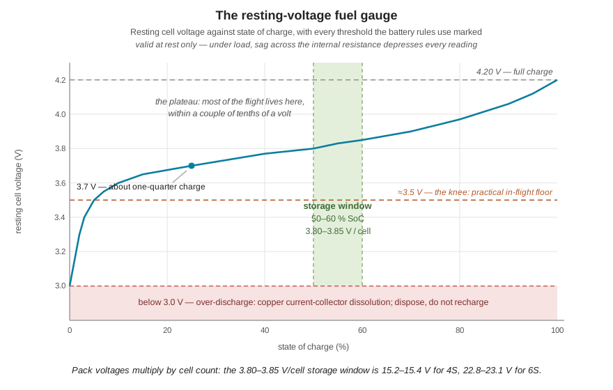
A cell’s voltage is the difference between its two electrode potentials, each set by how much lithium the electrode currently holds. The resting voltage therefore maps to state of charge — the curve of Figure 4.3: 4.20 V at 100 %, a long shallow plateau through the middle of the discharge — roughly 3.85 V near 55–60 %, 3.7 V around a quarter — and then a steep knee below about 3.5 V, where the remaining few percent drain away with the voltage falling fast. Three consequences of that curve shape run through all battery practice. First, voltage is a usable fuel gauge only because the mapping is repeatable — but only at rest; under load the reading is depressed by internal resistance, which is why in-flight voltage alarms are set conservatively. Second, the flatness of the plateau means most of the flight happens within a couple of tenths of a volt, so the 20 % speed variation per cell voltage computed in the previous chapter is concentrated at the ends of the flight. Third, the steep knee is why the practical floor is ~3.5 V per cell: below it there is almost no energy left to collect, and the damage threshold at 3.0 V is minutes away at flight loads.
4.4.3 Why storing a cell full degrades it
At full charge the cell is at its maximum chemical stress in both directions at once. The cathode is maximally delithiated — at a cell voltage of 4.20 V it sits near 4.3 V versus lithium, right at the oxidative stability limit of the carbonate electrolyte — and the graphite anode is maximally lithiated, sitting within a tenth of a volt of lithium metal itself and hungry to reduce anything that touches it. Both interfaces therefore run continuous parasitic side reactions: the electrolyte slowly oxidizes at the cathode surface and is slowly reduced into ever-thickening interphase layers at the anode. These reactions consume electrolyte and cyclable lithium (permanent capacity loss), thicken the interface films (rising internal resistance), and — the visible symptom — generate gaseous products, chiefly CO₂ and CO, which inflate the pouch. A “puffed” LiPo is the exhaust of its own electrolyte decomposition, and the puffing is doubly harmful: beyond marking lost capacity, the gas layer physically separates electrode from separator, lengthening the ionic path and raising resistance further.
Both reaction families are thermally activated and accelerate with state of charge, which is why the damage is a strong function of how full and how warm the cell sits. Typical published calendar-ageing measurements make the point numerically: a cell stored fully charged at room temperature loses on the order of 20 % of its capacity in a year, against roughly 4 % for the same cell stored near half charge — and both figures roughly double for each 10–15 °C of storage temperature. A charged pack left in a hot car combines the worst of both axes. The practical rule — charge shortly before flying, not days ahead — is this chemistry read backwards.
4.4.4 Why storing a cell empty destroys it
The empty end fails by a different and nastier mechanism. A cell landed at the ~3.5 V floor holds only a few percent of its capacity, and self-discharge does not stop at zero percent: the same parasitic reactions keep nibbling, and with the discharge curve’s knee already passed, the voltage now falls quickly and keeps falling. Below about 3.0 V per cell the cell enters territory its chemistry cannot tolerate. As the graphite gives up its last lithium, the anode’s potential climbs — and once it climbs to roughly 3.1 V versus lithium, the copper foil the anode is coated on becomes electrochemically unstable and begins to dissolve into the electrolyte as copper ions. This is not a metaphor: the current collector itself corrodes away.
The damage is twofold and irreversible. Capacity is lost outright, because the interphase layers and dissolution products consume lithium inventory that can never be recovered. Worse, a copper-contaminated cell is dangerous to recharge: charging drives the dissolved copper ions to plate back out as metallic copper wherever the field concentrates — including as filaments through the separator’s pores — creating internal micro-shorts. A micro-shorted cell self-discharges rapidly, heats internally, and is a thermal-runaway candidate sitting on a bench. This is why the correct disposition for a pack found deeply over-discharged after storage is disposal, not a “recovery charge,” whatever the charger’s recovery mode offers: the 3.0 V threshold is not where the battery stops working, it is where recharging it stops being safe. The familiar story of a pack that “stopped functioning after long-term storage” is this mechanism playing out in a drawer: a pack put away nearly empty drifts under 3.0 V within weeks, and every week below the threshold dissolves more copper.
4.4.5 The storage-charge window, justified
The two failure modes bracket an optimum. Full storage maximizes parasitic reaction rates; empty storage courts the copper cliff. The window in between — roughly 50–60 % state of charge, a resting voltage of about 3.80–3.85 V per cell (15.2–15.4 V for a 4S pack, 22.8–23.1 V for 6S; the shaded band in Figure 4.3) — is chosen to sit well down from the oxidative stress of the full cathode while banking a large energy margin above the damage threshold. The margin is worth computing, because it is the part of the rule people doubt. Take the book’s 5200 mAh pack, stored at 3.85 V per cell, about 55 % SoC — 2860 mAh in the bank. LiPo self-discharge runs on the order of 1–2 % of rated capacity per month, 52–104 mAh. Merely reaching the 20 % mark — still entirely healthy — means losing the difference between the 2860 mAh on hand and 20 % of capacity (1040 mAh), i.e. 1820 mAh, which takes \(1820/104 \approx 17\) months even at the pessimistic rate; reaching genuine danger takes years. Now run the same arithmetic for a pack tossed in the drawer as it came back from its last flight, resting near 3.5 V with perhaps 5 % — 260 mAh — remaining: at 52–104 mAh per month it is fully empty within a few months and dropping through 3.0 V soon after. The storage rule is not fussiness; it is the difference between a shelf life measured in years and one measured in weeks. Every mainstream hobby charger has a storage mode that charges or discharges the pack to this window automatically; ending a flying day by putting every pack into storage mode is the single highest-value battery habit there is.
Where the pack sits matters too, because the failure it guards against is thermal. Cool storage slows every parasitic reaction (the same Arrhenius factor working in your favour); dry storage protects the pouch laminate and connectors; and a fire-resistant container — a LiPo bag or steel ammunition box, vented rather than sealed, because containment must not become a pressure vessel — bounds the consequences if a damaged cell does run away. A cell in thermal runaway is its own oxidizer and cannot be starved like an ordinary fire; the container’s job is to keep one pack’s failure from propagating to the shelf above it.
4.4.6 Internal resistance: the health gauge
Everything that ages a cell — interphase growth, electrolyte loss, gas separation, copper contamination — shows up in one measurable number: internal resistance. It is measured from Ohm’s law with the pack as its own instrument: read the resting voltage, apply a known load, read the sag. A healthy modern 5 Ah pouch cell measures a handful of milliohms; call it 5 mΩ. Consider what happens as that triples to 15 mΩ — a typical end-of-life figure — on the aircraft sized in the previous chapter, whose four motors draw 80 A at full throttle.
At 80 A, the healthy cell sags \(80 \times 0.005 = 0.40\) V and dissipates \(80^2 \times 0.005 = 32\) W of internal heat; across a 4S pack, 1.6 V and 128 W. Ugly but sustainable for the seconds a full-throttle climb lasts. The aged cell sags \(80 \times 0.015 = 1.2\) V — from a 3.7 V plateau down to 2.5 V under load, deep past any voltage alarm — and dissipates 96 W per cell, 384 W per pack — against roughly 800 W actually delivered to the motors (\(4 \times 2.5\ \text{V} \times 80\ \text{A}\)), so nearly a third of the chemical power the pack produces is now cooking the pack itself. The symptoms pilots report — the pack that “sags,” triggers failsafes on punch-outs, comes back warm, and shows fine resting voltage — are all this one parameter. In hover the same aircraft draws about 17 A (\(252\ \text{W} / 14.8\ \text{V}\)), where even the aged pack sags only 0.26 V per cell, which is why a dying pack flies gentle missions convincingly and fails exactly when full performance is demanded. The C rating now reads as what it always was: a manufacturer’s claim that internal resistance is low enough to sustain a stated current — \(50\text{C} \times 5.2\ \text{Ah} = 260\) A for the book’s pack against an 80 A worst case — and the reason that rating erodes with age is that the resistance underneath it grows.
A battery log — pack serial, cycle count, per-cell internal resistance at each charge, post-flight resting voltages — costs a minute per flight and converts battery management from anecdote to data. Retirement criteria then stop being arguments: a pack leaves service when internal resistance has roughly tripled from new, when any cell puffs visibly or holds a resting voltage persistently out of balance with its siblings, or after any excursion below 3.0 V per cell, regardless of how it seems to perform afterwards.
Structure and chemistry between them settle what the aircraft can carry and how long it can stay up. They say nothing about what it knows while it is up there — and a frame stiff enough to keep its resonances clear of the rotors was, in the argument above, valuable mainly because of what it does for a sensor. Those sensors are the subject of the next chapter.
Two variations on the chemistry appear in drone work. LiHV cells shift the charge cutoff from 4.20 to 4.35 V per cell, buying roughly 10 % more energy per gram at the direct cost of intensified high-voltage electrolyte oxidation — the calendar-ageing penalty of this chapter’s “stored full” section, purchased deliberately, cycle after cycle. They suit racing, where packs live hard and die young, and are a poor trade for endurance platforms. In the opposite direction, endurance-oriented builds increasingly use cylindrical Li-ion cells (18650/21700 format), which reach ~250 Wh/kg at cell level — well above pouch LiPo — but with internal resistance too high for aggressive discharge: a fine trade at a survey platform’s steady 2–3C hover draw, a disqualifying one for anything that needs punch. The selection logic is this chapter’s internal-resistance arithmetic with different inputs, which is the point: chemistry choices, like material choices, are the same trade study with the same handful of numbers.
4.5 Check Your Understanding
- A colleague proposes 3D-printing replacement frame arms in PLA at the same dimensions as the carbon originals, arguing that PLA is “strong enough” since the arms rarely break in flight. Using \(E_{\text{CF}} = 50\) GPa, \(E_{\text{PLA}} = 3.5\) GPa, evaluate the proposal on the correct figure of merit.
Strength is the wrong figure of merit — arms are sized by stiffness, for geometry-holding and for keeping structural resonances above the propellers’ excitation. At identical geometry, a cantilever’s first resonant frequency scales as \(\sqrt{E/\rho}\): with \(E/\rho\) of 31 MJ/kg for quasi-isotropic carbon against 2.8 MJ/kg for PLA, the printed arm’s first mode drops by a factor of \(\sqrt{31/2.8} \approx 3.3\), likely landing inside the 90–180 Hz band the propellers excite, corrupting the IMU and destabilizing the attitude loop. Matching the carbon arm’s bending stiffness instead requires \((50/3.5)^{1/3} = 2.4\) times the thickness, and \(2.4 \times (1.24/1.6) \approx 1.9\) times the mass — roughly doubling arm mass on an aircraft whose hover power scales as \(m^{3/2}\). Additionally, PLA’s ~60 °C glass transition disqualifies it outdoors in summer sun. Print the camera bracket; buy the carbon arm.
- A 6S pack will not be flown for three weeks. State the storage voltage for the whole pack, the approximate state of charge it represents, and the two failure mechanisms the storage window is positioned between.
Storage is 3.80–3.85 V per cell, so \(6 \times 3.80\) to \(6 \times 3.85\) = 22.8–23.1 V for the pack, about 50–60 % state of charge. The window sits below the high-SoC regime — where the near-4.3 V (vs. lithium) cathode continuously oxidizes electrolyte, generating gas (puffing), consuming lithium inventory, and raising internal resistance — and far above the low-SoC cliff, where self-discharge drags the cell below 3.0 V and the anode potential rises high enough (~3.1 V vs. lithium) to dissolve the copper current collector. Three weeks at full charge is survivable but pointlessly costly; three weeks starting from a nearly empty pack could cross the 3.0 V threshold. Storage mode covers both.
- Explain why a LiPo cell found at 2.6 V after winter storage should be disposed of rather than recharged, even if a charger’s “recovery mode” will accept it.
Below about 3.0 V, the delithiated graphite anode’s potential climbs to the point (~3.1 V vs. lithium) where the copper foil it is coated on becomes electrochemically unstable and dissolves into the electrolyte as copper ions. Recharging then drives those ions to redeposit as metallic copper, including as filaments through the separator’s pores, creating internal micro-shorts. The cell may accept charge and read a normal voltage, but it will self-discharge abnormally, heat internally, and carries an elevated risk of thermal runaway during charge — precisely when it is on a bench, indoors, possibly unattended. The capacity lost to the excursion is also unrecoverable. Recovery mode can restore the voltage; it cannot un-dissolve the copper.
- A cell rests at 3.75 V; under a 30 A load it reads 3.45 V. Compute its internal resistance and its internal heating at that load. The same cell measured 5 mΩ when new — what does the comparison tell you, and what would you check next?
\(R = \Delta V / I = (3.75 - 3.45)/30 = 0.30/30 = 10\ \text{m}\Omega\); heating is \(I^2R = 900 \times 0.010 = 9\) W in this one cell at 30 A. Resistance has doubled from new — meaningful ageing, though short of the tripled-from-new retirement criterion. Next: measure every cell in the pack, not just one, because degradation is rarely uniform — a single outlier cell dominates pack sag and is the first to hit the under-load voltage floor; check per-cell resting voltages for balance drift and the pouch for the onset of swelling; and project the trend from the pack’s log. A pack at 2× resistance still flies, but it should be demoted from performance flights and watched.
- A printed nylon landing-gear leg survives crashes that snap its carbon predecessor, yet this chapter assigns arms to carbon and only fittings to printing. Reconcile the two facts.
The two parts have different jobs. An arm’s job is stiffness in normal flight — holding rotor geometry and keeping resonances above the excitation band — and there carbon’s order-of-magnitude specific-stiffness advantage is decisive; the arm is not supposed to absorb crash energy, and carbon could not do so anyway, being elastic to fracture at ~1 % strain. A landing leg’s job is the opposite: it exists precisely to absorb impact energy, which favours a tough material with large plastic strain — nylon’s elongation beyond 100 % lets it deform and recover or fail cheaply — and its stiffness barely matters. The general rule: match the material’s failure behaviour to the component’s role. Stiff and brittle for structure that must not flex; tough and compliant for structure that must survive abuse; and print the latter with load in the layer plane so layer separation is not the governing failure.
- Using the calendar-ageing figures in this chapter, estimate the capacity remaining after one year for two identical packs: one stored fully charged on a sunny windowsill (averaging ~35 °C), one at storage charge in a cool basement (~15 °C). Assume ~20 %/year loss at 100 % SoC and ~4 %/year at storage charge, both at 25 °C, with rates doubling per 10–15 °C.
The windowsill pack is stored full and roughly 10 °C above the reference, so its ~20 %/year loss roughly doubles to ~40 %: about 60 % of capacity remains, and the pack has likely also puffed and gained resistance — effectively ruined for flight loads. The basement pack is at storage charge and ~10 °C below reference, halving its ~4 %/year to ~2 %: about 98 % remains. The two habits differ by a factor of about twenty in annual degradation, which is the quantitative content of “storage charge, cool, dry.” (Both estimates are order-of-magnitude — the point is the ratio, not the decimals; self-discharge over the year is comfortably covered by the storage-charge margin computed in the chapter.)
4.6 Try It
Part 1 — a materials decision, defended with numbers. Pick one crash-exposed component of a drone you have access to (or the book’s 500 mm-class platform): an arm, a camera mount, a leg, an antenna mast. Decide what its actual job is — stiffness, strength, or energy absorption — and choose a material with the table in this chapter, showing the specific-stiffness or specific-strength arithmetic. If you choose a printed part, state the print orientation and justify it from the load path and the layer-separation mechanism; estimate the cost and time per replacement against the carbon alternative, and state the crash rate at which each option wins. If a printer is available, print the part in two orientations — load in-plane and load across layers — and break both by hand: the difference you feel is the 30–70 % interlayer knockdown made tangible.
Part 2 — a battery standard operating procedure. Write a one-page battery SOP for a small drone program, and make every rule in it traceable to a mechanism from this chapter. It should specify: the storage window in volts per cell and why (both failure modes, with the self-discharge arithmetic for your pack’s actual capacity); when packs are charged relative to flights; the container and location for storage and charging; per-flight log fields (cycle count, per-cell internal resistance, post-flight resting voltages); and numeric retirement criteria (resistance multiple from new, balance drift, puffing, any sub-3.0 V excursion). Then take a real pack, measure its per-cell internal resistance from voltage sag under a known load, and start the log with an entry. A rule you can defend with a mechanism will survive contact with a busy flight line; a rule that is only a rule will not.
Related Lab: See Appendix B for the lab assignment that applies this chapter’s concepts.