8 Putting It Together: The Autonomous Drone Stack
Part I has approached the drone six times from six directions, and each approach stopped where the next one began. The Commercial Drone Landscape chapter established what the vehicle is for and why the industry converged on commodity hardware carrying custom software. The Anatomy of a Multirotor chapter sized a specific airframe from a specific mission. The Materials and Power chapter explained what that airframe is made of and what its battery will tolerate. The Sensing the World chapter followed a measurement from a silicon flexure to a fused attitude estimate. The Airspace Law chapter established the legal envelope the finished vehicle must fly inside. And the previous chapter bolted a Linux computer to the airframe and proved, with a MAVLink heartbeat, that the computer and the autopilot can talk.
What has not happened yet is assembly. Six correct components lying on a bench are not an aircraft, and an aircraft is not a system: the interesting properties of an autonomous vehicle — that it can decide, that it can be trusted, that it fails in bounded ways — are properties of the arrangement, not of any part. This chapter makes that arrangement explicit. It lays out the complete vehicle in one labeled figure, names the single control pattern that repeats at every level of it, walks one mission from the pre-flight briefing to the landing, and sketches — at altitude, leaving the detail to Part V — the software architecture that sequences it.
The system in question is the Goose Management System, the running example the Commercial Drone Landscape chapter introduced as the wildlife-management vertical in miniature: an aircraft that searches a protected area, detects geese with onboard computer vision, deters them, evades any bird that contests the airspace, and returns. That chapter answered its own five questions about the mission in a sentence — the payload is a depth camera and a companion computer, the binding constraint is visual line of sight plus wildlife-disturbance permission, the corrupting physics is illumination and background clutter in the detector, the workflow is a search grid transitioning into a pursuit, and the deliverable is the deterrence itself. Those answers can now be spent rather than merely stated, because every noun in them has been developed in the intervening chapters.
8.1 Learning Objectives
- Assemble the components developed separately across Part I into one labeled vehicle, and state what each contributes to a mission rather than merely what it is.
- Explain the sense–think–act loop, identify the three nested rates at which it runs on an autonomous multirotor, and name the hardware that closes each one.
- Trace the running example’s mission end to end — brief, launch, search, detect, deter, evade, return — identifying at each phase which Part I result binds: endurance, thrust margin, sensor accuracy, or regulation.
- Convert the platform’s power and energy numbers into a mission time budget with an explicit reserve, and justify the battery condition at which an autonomous vehicle must abandon its mission and return.
- Distinguish topics from services at the level needed to read an autonomy architecture, and explain why safety monitoring is placed in a process independent of the mission logic.
- State precisely what Part I has settled and what it has deliberately left open, and explain why everything from Part II onward is software running on the companion computer.
8.2 Key Vocabulary
- Sense–think–act loop — the fundamental cycle of any autonomous system: measure the world, compute a decision from the measurement, command actuators that change the world, and measure again. Every layer of an autonomy stack is an instance of it, differing only in rate and in the consequence of missing a deadline.
- Autonomy stack — the layered software that converts a remotely piloted vehicle into a self-directed one: state estimation and stabilization at the bottom, perception and guidance in the middle, mission sequencing and safety supervision at the top.
- Offboard control — a flight-controller mode in which the autopilot stops taking direction from a human pilot or a preloaded waypoint list and instead follows a continuous stream of position, velocity, or attitude setpoints supplied by an external computer, reverting to a safe behavior if that stream stops.
- ROS 2 node (Robot Operating System 2) — an independent operating-system process in the ROS 2 middleware that performs one job and exchanges data with other nodes only through named, typed channels, so that nodes can be developed, tested, restarted, and replaced independently.
- Topic — a ROS 2 publish–subscribe channel carrying a continuous stream of messages from one publisher to any number of subscribers, with no acknowledgment; the right mechanism when data is always flowing and only the latest value matters.
- Service — a ROS 2 request–response channel in which a caller asks one node to perform a discrete action and waits for its reply; the right mechanism when an action happens once and the caller must know it succeeded before proceeding.
- Failsafe monitor — a supervisory process that watches a small set of safety-critical quantities and can override whatever is currently commanding the vehicle. Its defining property is independence: it must not share a failure mode with the logic it supervises.
- Mission time budget — the usable flight time remaining after a reserve is set aside, allocated in advance across the phases of a mission, and the quantity against which an autonomous vehicle’s decision to continue or return is actually made.
8.3 The Vehicle Part I Built
Figure 8.1 shows the assembled aircraft from above, with every component Part I selected in the place it physically occupies.
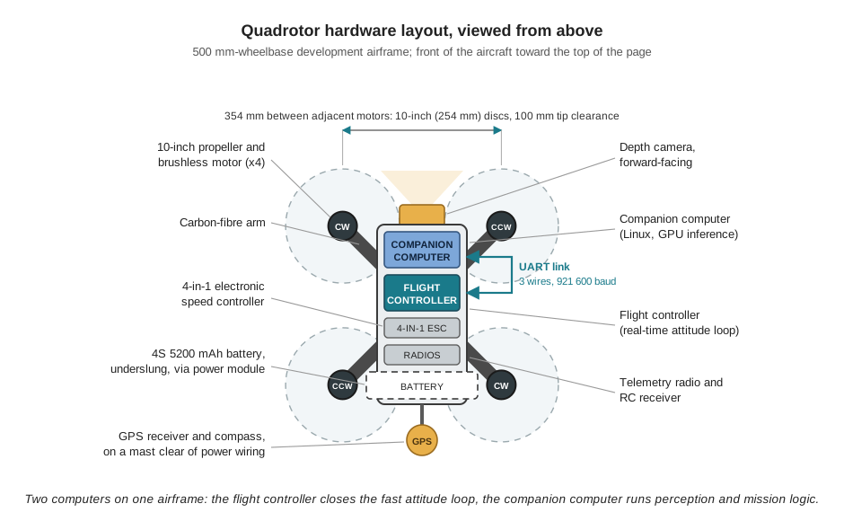
The figure is worth reading against the arithmetic that produced it. The 500 mm wheelbase puts adjacent motors 354 mm apart, which is what allows 10-inch propellers with 100 mm of tip clearance and forbids anything larger; the Anatomy of a Multirotor chapter derived that geometry and then followed it through to 5,425 RPM in hover, 192 W of shaft power, and 252 W of electrical draw at 1.7 kg empty. The arms are carbon because the Materials and Power chapter’s specific-stiffness argument leaves no alternative for a structure whose resonances must stay clear of the 90 Hz and 181 Hz the propellers inject; the camera bracket and the tray under the companion computer are the printed parts that same argument permits. The two counter-rotating pairs marked in the figure are the whole mechanism of yaw control, and their symmetry is why four rotors is the minimum for full attitude control with fixed-pitch blades.
Three items in the figure exist for the mission rather than for flight, and together they are the 500 g of autonomy payload the sizing calculation carried: the Jetson Nano companion computer, the Intel RealSense D455 depth camera at the nose, and the mounting hardware that holds them. The previous chapter justified the Jetson against the cheaper, lighter Raspberry Pi with one criterion — a goose has to be recognized by a neural network running on the aircraft, and no CPU-only board runs one at a useful frame rate — and it was explicit that the choice is paid for twice, in the mass that shortens every flight and in the watts that overrun the 12 W avionics allowance the power budget assumed. The bill is exact: adding the payload takes all-up weight from 1.7 kg to 2.2 kg, raises hover draw from 252 W to 365 W by the \(m^{3/2}\) scaling, and cuts hover endurance from 14.7 minutes to 10.1 minutes. Every mission decision in this chapter is made inside those ten minutes.
The remaining components are there to make the aircraft legal, recoverable, and observable rather than to make it fly. The GPS receiver and compass ride a mast because the magnetometer measures tens of microtesla and the power wiring beneath it carries tens of amperes. The power module between the battery and the distribution board measures pack voltage and current, which is what turns the Materials and Power chapter’s battery arithmetic from a bench exercise into a quantity the autonomy software can act on in flight. The telemetry radio and the RC receiver are the other two of the three command paths the previous chapter enumerated, and both stay live throughout: the RC link is the safety pilot’s override, which is the Airspace Law chapter’s layered-margin logic implemented in hardware rather than in policy.
8.4 One Loop, Nested at Three Rates
Underneath the component inventory there is exactly one architectural idea, and Figure 8.2 is all of it. An autonomous system measures the world, decides what the measurement implies for its goal, acts to change the world, and measures again. Everything else is a question of what is being measured, how hard the decision is, and how fast the cycle must close.
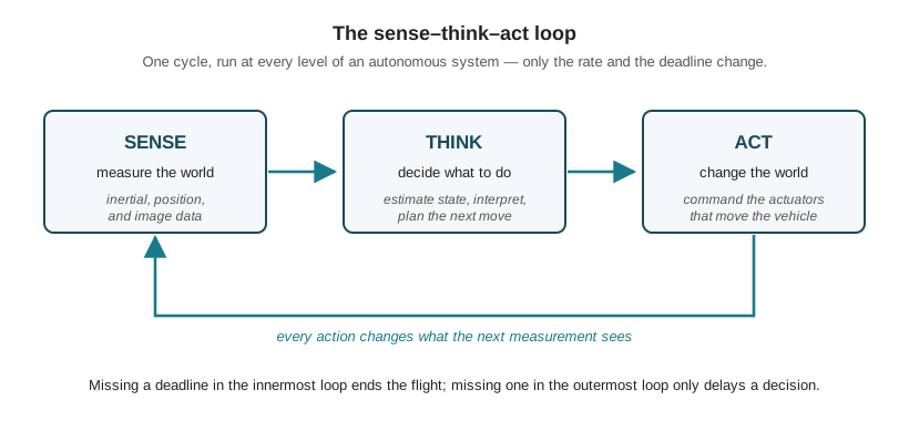
On this aircraft the loop runs at three rates simultaneously, nested one inside another, and the hardware in Figure 8.1 is partitioned along exactly those nesting lines.
The attitude loop, on the flight controller, at kilohertz. The Pixhawk reads its inertial measurement unit over a dedicated SPI bus — the Sensing the World chapter did the bandwidth arithmetic showing why the fast, lonely sensor gets its own bus while the slow, sociable barometer and magnetometer share I2C — runs the extended Kalman filter that fuses gyroscope, accelerometer, magnetometer, barometer, and GPS into an attitude and position estimate, and resolves the error between commanded and actual attitude into four motor commands. This loop cannot be late. A quadrotor holds no attitude on its own; a stall of a tenth of a second is the end of the flight. That is precisely why it runs on a microcontroller whose scheduler is designed to exclude anything unpredictable, and why nothing else is allowed onto that processor.
The perception loop, on the companion computer, at camera rate. Frames arrive from the depth camera at tens of hertz, a neural network decides whether a goose is present, and a target position is published for anything that cares. Missing a frame here costs nothing but a frame; the vehicle is still flying, still stable, still where it was. The deadline is soft, the computation is enormous, and the hardware is chosen accordingly.
The mission loop, on the companion computer, at roughly one hertz. Given everything sensed so far, should the vehicle keep searching, close on a target, execute the deterrence maneuver, evade, or go home? A decision deferred by a second at this level is a decision deferred by a second; nothing falls out of the sky.
The seam between the two computers is the three-wire UART the previous chapter wired and verified, and it is worth being precise about what that seam can and cannot carry, because the bandwidth decides the architecture. At 921,600 baud in the standard 8N1 framing, the link moves about 90 kB/s. A stream of position setpoints — a few dozen bytes at a few tens of hertz — occupies a fraction of a percent of that, so commanding the vehicle across the seam is comfortable. Moving imagery across it is not: a 640 × 480 colour frame is 921,600 raw bytes, and thirty of them per second is roughly 27 MB/s, some three hundred times the link’s capacity. Even aggressively compressed to a few megabits per second, video would still exceed it, and the telemetry radio to the ground is slower again by orders of magnitude. This is the quantitative version of the argument the Commercial Drone Landscape chapter made about cheap onboard compute: perception must run where the pixels already are. The camera talks to the companion computer over USB, the companion computer talks to the flight controller over three wires, and the only things that cross those three wires are decisions.
8.5 The Mission, End to End
With the platform and the loop in place, one flight can be told properly. Each phase below names the Part I result that binds it — the constraint that decides whether the phase is possible at all.
8.5.1 Before the battery is connected
Nothing has been built yet that removes the human obligations of the Airspace Law chapter. A research flight is non-recreational by definition and therefore a Part 107 operation: a certificated remote pilot in command is present, the aircraft is registered and its actual weight recorded, and the flight is logged. The crew confirms airspace status, checks current NOTAMs and Temporary Flight Restrictions through a briefing source, and captures the evidence. PAVE and I’M SAFE are run and answered out loud. Wildlife-disturbance permission — the second half of the running example’s binding constraint, and the half that has nothing to do with aviation — is in hand. The RC transmitter is on and its override tested before anything is armed.
None of this is preamble to the engineering. It is the reason the vehicle in Figure 8.1 is shaped as it is: an aircraft that must stay within visual line of sight is an aircraft whose search area is bounded by what a person can see, and an aircraft under a 400-foot (122 m) ceiling is one whose sensor must resolve a bird from a few tens of metres rather than from any altitude that would be convenient.
8.5.2 Launch and handoff
The vehicle is armed and takes off under the flight controller’s own control, with the safety pilot on the sticks. The barometer records pad pressure at arming as its reference, which is why altitude is reported relative to the launch point and not against a weather-dependent sea-level datum; the same paragraph of the Sensing the World chapter warned that the propellers’ own wash, intensified by ground effect, makes barometric altitude least trustworthy exactly during takeoff and landing, which is why the climb is flown on the fused estimate rather than on pressure alone.
At a safe altitude the flight controller is switched to offboard mode and the companion computer begins publishing setpoints. This is the handoff the whole of Part I has been building toward: from this instant the decisions come from a process rather than from a person. Offboard mode carries its own protection — if the setpoint stream stops for more than a fraction of a second, the autopilot does not coast, it falls back to a safe behavior — and that protection is the first of several places where the system’s safety does not depend on the autonomy software being correct.
8.5.3 Search
The vehicle flies a search pattern over the protected area. Two Part I results set its shape. Altitude is fixed from below by the pixels-on-target requirement the Commercial Drone Landscape chapter identified for every wildlife survey — a bird must span enough pixels for the detector to classify it, which is the ground-sample-distance relation read backwards — and from above by the 122 m regulatory ceiling and by the range at which the depth camera still returns useful depth. In practice the search leg is flown a few tens of metres above ground: high enough to see a useful swath, low enough to resolve a goose, and nowhere near the legal limit. The pattern’s own geometry, and the question of what an efficient search looks like when the target moves, belong to Part IV.
The second result is the clock, and it is the tighter of the two. The platform’s 10.1 minutes is a hover figure computed for a new pack in still air; forward flight and maneuvering cost more, and wind costs more again, so it is an optimistic ceiling rather than a plan. Holding back a 25 % reserve leaves about 7.6 minutes of mission, which has to be allocated before takeoff rather than discovered in flight:
| Phase | Allocation | What sets it |
|---|---|---|
| Climb and transit to the search area | 1.0 min | Distance from the launch point, bounded by visual line of sight |
| Search leg | 3.5 min | Area to be covered at the chosen altitude and speed |
| Approach and deterrence | 2.0 min | Time to close on a detection and complete the maneuver |
| Return and land | 1.0 min | Transit back plus a controlled descent |
| Reserve (held, not spent) | 2.6 min | Wind, a second detection, a diverted landing |
Seven and a half allocated minutes against a ten-minute battery is not a generous budget, and reading it honestly changes the design: the search pattern must be sized to the time available, not the time available discovered after the pattern is chosen. This is the payload–endurance exchange rate of the Anatomy of a Multirotor chapter arriving as a mission constraint. Every gram the autonomy hardware added was paid for here.
8.5.4 Detection
The detector, running on the Jetson, publishes a target position when a goose appears in frame. The depth camera earns its mass at this moment: a monocular camera reports a bearing to a detected object and leaves its range ambiguous, while a depth camera returns range directly, so the target can be placed in the vehicle’s own coordinates without maneuvering to triangulate. How the network is trained, compressed, and run inside the Jetson’s power envelope is the subject of Part III; what matters here is that the estimate is produced onboard, at frame rate, and that everything downstream consumes it as a stream rather than requesting it.
8.5.5 Deterrence
Once a target is localized, authority over the vehicle’s motion transfers from the search behavior to the deterrence behavior, which closes on the bird and executes the maneuver that moves the flock along. Two constraints bound it. The first is the wildlife-disturbance framing of the Commercial Drone Landscape chapter: the same disturbance that makes deterrence effective is a documented stressor on the animals, which is why the permission exists and why the maneuver is designed to be the least disturbance that works — an engineering requirement, not a courtesy. The second is separation. The vehicle must not contact a bird, and the reason is quantitative: the Anatomy of a Multirotor chapter showed that a quadrotor which loses one of four rotors cannot produce net thrust with zero net moment and simply falls, where a hexacopter would degrade. A quadrotor has no graceful failure to fall back on, so separation distance is monitored continuously and enforced by something other than the behavior that is trying to close the distance.
8.5.6 Evasion
If a goose contests the airspace and closes on the aircraft, the vehicle breaks away — and what it can do is set by thrust margin. Loaded to 2.2 kg against roughly 4.0 kgf of static thrust, the aircraft’s thrust-to-weight ratio is about 1.8, so hover consumes 55 % of available thrust and the surplus available for acceleration is
\[a_{\max} = (\mathrm{TWR} - 1)\,g = (1.8 - 1)(9.81) = 7.8\ \text{m/s}^2.\]
A 5 m evasive climb therefore takes at least \(t = \sqrt{2h/a} = \sqrt{2(5)/7.8} = 1.1\ \text{s}\), arriving at about 8.8 m/s — and that is an optimistic bound, ignoring the time the rotors need to spool up and the drag of a fast vertical climb. The number is worth carrying because it tells the behavior designer what is physically purchasable: an evasion that must complete in half a second is not available on this airframe at this weight, and the remedy is a lighter payload or a larger aircraft, not a cleverer state machine.
The maneuver also costs the pack its worst moment. Full throttle draws roughly 80 A, a 15 C discharge for the 5.2 Ah pack, and at that current the Materials and Power chapter’s internal-resistance arithmetic becomes operationally visible: a healthy 5 mΩ cell sags 0.40 V, while an aged 15 mΩ cell sags 1.2 V, dropping from the 3.7 V plateau to about 2.5 V under load — well past any naive low-voltage alarm, on a pack that looked entirely healthy in hover at 17 A. A dying pack flies gentle missions convincingly and fails exactly when the vehicle needs to evade.
8.5.7 Return, land, and the failsafe that watches all of it
The mission ends deliberately: the vehicle returns to the launch point and lands, or triggers return-to-launch early. The decision to end early belongs to the failsafe monitor, and the threshold it uses is a direct consequence of the paragraph above. Triggering on measured pack voltage under load is unsound, because sag under load is a function of the pack’s age as much as its charge, and the aged pack’s 1.2 V of sag would fire the alarm in a climb and clear it in a hover. The defensible trigger is consumed capacity, integrated from the current the power module reports, checked against a resting-voltage floor referenced to the 3.5 V-per-cell practical limit — with the reserve in the budget table above as the quantity actually being protected. The monitor watches separation distance on the same footing, and it can override whichever behavior is flying the aircraft.
On landing, the barometer becomes untrustworthy again in ground effect, the RC pilot is ready to take the vehicle back, and the flight log becomes the input to the diagnostics of Part V. The pack goes into storage charge, at 3.80–3.85 V per cell, before the crew leaves the field.
8.6 The Software Above the Wire
The autonomy stack on the companion computer is not one program. It is a set of independent ROS 2 nodes — separate operating-system processes, each with one responsibility — communicating only through named channels. The modularity is a deliberate engineering decision with two payoffs: nodes can be developed, tested, and replaced independently, and a crash in one does not take down the others. The second payoff is the one that matters for safety.
ROS 2 offers two communication mechanisms, and the choice between them is not stylistic. Services are request–response: one node asks another to perform a discrete action — arm the vehicle, enter offboard mode, trigger return-to-launch — and waits for an acknowledgment before proceeding. Topics are publish–subscribe: a node publishes a stream of messages — target position, distance remaining, battery state — and any number of nodes subscribe, with no acknowledgment exchanged. The rule of thumb follows from what each contract guarantees. Use a service when the action happens once and the caller must know it succeeded; use a topic when data is always flowing and only the latest value matters. Arming is the archetypal service: a mission that advances without confirming that the vehicle actually armed is a mission that has lost track of reality. Target position is the archetypal topic: it changes every frame, several nodes need it, and a stale value is worse than no value.
Mapped onto those two mechanisms, the running example’s stack resolves into four functional groups: a mission sequencer that holds the state machine and announces which behavior currently has authority; a vehicle interface that translates high-level requests into autopilot commands over the link verified in the previous chapter; the motion behaviors — search navigation, deterrence, evasion — that generate setpoints when they hold authority; and the Failsafe node, which subscribes to battery state and separation distance and can override any of the others. The Failsafe node is the reason the modularity is worth its overhead. If the safety checks lived inside the mission sequencer, then a hung state transition or an unhandled exception in the sequencer would disable the checks at the exact moment the system was misbehaving. As a separate process it shares no failure mode with the logic it supervises, and — as the Sensing the World chapter noted from the other end of the pipeline — it consumes the flight controller’s fused state estimate rather than raw sensor readings, trusting the estimator to have already fought the battles that chapter described.
That sketch is deliberately shallow. The node-by-node architecture, the message types on each channel, the state machine’s transitions, and what happens when two nodes claim authority at once are the subject of the Systems Architecture chapter in Part V, which returns to this same system with the whole book behind it. The purpose here is only to make the shape legible: independent processes, streams for data, calls for decisions, and a supervisor outside the thing it supervises.
8.7 What Part I Settled, and What Comes Next
The previous chapter framed the change this Part has been working toward in one line: with a radio transmitter, the drone is a vehicle you drive; with a companion computer, it is a platform you program. Part I has now delivered that platform completely. The airframe is sized and its geometry fixed. The materials are chosen and the battery’s chemistry understood well enough to specify how it is charged, stored, and retired. The sensors are characterized down to their bias and noise, and their fusion into a usable state estimate is no longer a mystery. The regulatory envelope is mapped, and the human procedures that keep an operation inside it are specified. A general-purpose Linux computer sits on the aircraft with a verified channel to the machine that flies it.
That is the entire physical contribution. Every remaining question in this book is a question about software running on that computer, and the Parts divide along the loop of Figure 8.2. Part II takes the innermost cycle and makes it quantitative — feedback control, the PX4 autopilot and the MAVLink protocol that carries commands across the wire, the MAVSDK and ROS 2 interfaces through which a program commands flight, and the geofences and failsafes that re-express the Airspace Law chapter’s rules as parameters the firmware enforces rather than habits a pilot maintains. Part III takes the perception cycle: how images become tensors, how a network is trained and then compressed to run inside the Jetson’s power and memory budget, and how inference latency bounds the behaviors the vehicle can support. Part IV takes the outermost cycle: search and coverage patterns, path planning, the behavior architectures that sequence discrete actions, and coordination among several aircraft. Part V puts them back together and asks the harder questions — integration, field diagnosis from telemetry logs, and the ethics of an aircraft that decides for itself.
The hardware is finished; from here the work is code. The vehicle in Figure 8.1 will not change again. What changes is how much of its behavior a program, rather than a person, is responsible for.
8.8 Check Your Understanding
- The loaded aircraft achieves 10.1 minutes of hover endurance. A colleague proposes planning a mission that uses 9 minutes of it, arguing that a one-minute reserve is enough since the vehicle lands where it took off. Evaluate the proposal, and state what the 10.1-minute figure does and does not include.
The 10.1 minutes is a hover figure for a new pack in still air, computed from 61.6 Wh of usable energy against 365 W of hover draw. It excludes the extra power of forward flight and maneuvering, excludes wind, and assumes a pack whose internal resistance has not risen with age — all of which push actual endurance down, never up. A one-minute reserve is therefore not a reserve at all: it is smaller than the error in the estimate it is protecting against. The 25 % reserve used in the budget table (about 2.6 minutes) covers the modelling error, an unplanned second detection, and a diverted landing. The general principle is that a reserve protects against the uncertainty in the number it is subtracted from, so a figure known only to within 20 % cannot be planned to within 10 %.
- Explain, with arithmetic, why the neural network that detects geese must run on the companion computer rather than on a ground station receiving the video stream.
Because the imagery cannot leave the aircraft fast enough. A 640 × 480 colour frame is \(640 \times 480 \times 3 = 921{,}600\) bytes; at 30 frames per second that is roughly 27 MB/s. The wired UART between the companion computer and the flight controller carries about 90 kB/s at 921,600 baud — some three hundred times less — and the telemetry radio to the ground is slower again by orders of magnitude. Even heavily compressed to a few megabits per second, the stream would still exceed the serial link and would be fragile over a range-limited radio. The bandwidth asymmetry decides the architecture: pixels stay where they are produced, and only decisions — target positions, setpoints, mode changes, a few dozen bytes at a time — cross the wire. This is also why the mission does not require a ground link to proceed.
- The aircraft weighs 2.2 kg loaded and has about 4.0 kgf of static thrust. Compute the maximum vertical acceleration available for an evasive climb and the time to gain 4 m of altitude. Then state what would change if 300 g of additional payload were fitted.
Thrust-to-weight is \(4.0/2.2 = 1.8\), so the surplus acceleration is \((1.8-1)(9.81) = 7.8\ \text{m/s}^2\) and a 4 m climb takes at least \(t = \sqrt{2(4)/7.8} = 1.01\ \text{s}\) — optimistic, since it ignores rotor spool-up and drag. Adding 300 g takes the aircraft to 2.5 kg. Thrust-to-weight falls to \(4.0/2.5 = 1.6\), surplus acceleration to \((0.6)(9.81) = 5.9\ \text{m/s}^2\), and the same climb now takes \(\sqrt{8/5.9} = 1.17\ \text{s}\) — 16 % slower. Endurance suffers at the same time: shaft power scales as \(m^{3/2}\), so \(192 \times (2.5/1.7)^{3/2} = 343\) W of shaft power gives \(343/0.8 + 12 = 440\) W of electrical draw and \(61.6/440 = 0.140\) h, about 8.4 minutes, down from 10.1. Two independent constraints degrade together, which is the recurring shape of the payload argument.
- A team proposes triggering return-to-launch whenever measured pack voltage drops below 3.5 V per cell. Explain why this is unsound on this aircraft, and describe a defensible alternative.
Measured voltage under load is depressed by internal resistance, and internal resistance rises with age. A healthy 5 mΩ cell sags 0.40 V at the 80 A of a full-throttle maneuver; an aged 15 mΩ cell sags 1.2 V, taking it from the 3.7 V plateau to about 2.5 V under exactly the load the vehicle experiences during an evasion. The threshold would therefore fire spuriously during every aggressive maneuver on an aged pack and clear again in hover, and would fire at genuinely different states of charge depending on the pack’s age — the trigger would be measuring the wrong thing. The defensible alternative integrates current from the power module to track consumed capacity against the pack’s known usable energy, protects the planned reserve rather than a voltage number, and uses a resting per-cell voltage floor as a cross-check rather than as the primary trigger.
- The vehicle arms through a service call but receives its target position on a topic. Justify each choice, and predict the failure mode if the two mechanisms were swapped.
Arming is a discrete action whose success must be known before anything else proceeds, which is exactly the request–response contract of a service: the caller blocks until the vehicle confirms it is armed. Target position is a continuously changing quantity with several consumers, where only the newest value has any use — the publish–subscribe contract of a topic, which delivers to every subscriber without the publisher knowing who they are. Swapped, an “arm” topic would give the mission sequencer no confirmation, so it would advance to takeoff on the assumption that a message it published had been acted on; and a “target position” service would force each consumer to poll independently, delivering different, stale values to different nodes between requests, and coupling the detector’s rate to its callers’ request patterns.
- The Failsafe node runs as a separate process rather than as a check inside the mission sequencer, and it consumes the flight controller’s fused state estimate rather than raw sensor data. Give the reason for each design decision.
Separation of process is about failure independence. If the safety checks lived inside the mission sequencer, any defect that hung or crashed the sequencer — a logic bug, an unhandled exception, a deadlocked transition — would silence the safety checks at precisely the moment the system was misbehaving, which is when they are needed. As an independent process, the monitor shares no failure mode with the logic it supervises and can still force a hover, a return-to-launch, or an abort. Consuming the fused estimate rather than raw sensor data is about not duplicating a solved problem: the flight controller’s extended Kalman filter already tracks sensor biases, weights each measurement by its current uncertainty, and rejects outliers. A safety monitor that read raw accelerometers would have to re-solve estimation badly, and a monitor that reasons from a worse estimate than the vehicle is flying on is not a safeguard.
8.9 Try It
Part 1 — draw the system from memory, then find what binds it. Without looking back at Figure 8.1, sketch the aircraft from above and label every component you can recall, then annotate each label with the chapter of Part I that chose or sized it and the one number that decision turned on — the wheelbase that capped propeller diameter, the specific stiffness that forced carbon, the frame rate that forced a GPU, the sag under load that forced a current-integrating failsafe. Compare against the figure and note what you omitted; the omissions are usually the components that exist for legality or observability rather than for flight, which is itself worth noticing.
Part 2 — rebuild the mission time budget for a different mission. Take the same platform and change one thing: a site twice as far from the launch point, or a search area twice as large, or a payload 200 g heavier. Recompute endurance where the payload changed, using the \(m^{3/2}\) power scaling and 80 % motor-and-ESC efficiency with a 12 W avionics allowance, then rebuild the phase allocation table with a reserve you can defend. If the budget does not close — and for at least one of these three changes it will not — identify the cheapest way to make it close, and be specific about what you are trading: a smaller search area, a lower search altitude, a second battery and a landing between legs, a lighter camera, or a larger airframe. Write one paragraph stating which Part I result you are spending to buy the change, and one sentence on what the failsafe threshold must become as a result.
Related Lab: No lab currently maps to this chapter.