23 Harassment Pattern Generation: Designing Deterrent Flight Paths
The previous chapter closed on a promise: throughout the maneuvers this chapter designs, there will still be a target to fly around. The two-loop tracking architecture keeps the goose in frame and localized — the inner loop re-aims the camera at frame rate, the outer loop maintains a world-frame estimate — and the mission machine’s HARASS_TARGET state stands ready with an entry guard, a dwell-time exit, and stash-and-resume semantics under preemption. Every piece of scaffolding is in place except the thing being scaffolded. What, exactly, should the aircraft do once it is on station over a flock of geese it can see and localize?
The question deserves more care than “fly at them until they leave,” and this chapter’s answer has three layers. The first is behavioral: a deterrent flight path is an argument made to an animal, and it only persuades if it is phrased in the animal’s own threat grammar — which approach geometries read as danger, why a cohesive flock is easier to move than a scattered one, and why the goal is herding, not pursuit. The second is geometric: the argument is delivered as parametric trajectories — an orbit, a swoop, a figure-8, a herding vector — each with a small set of numbers (radius, speed, approach angle, minimum separation) that can be tuned, logged, and bounded. The third layer is the one that makes the other two admissible at all: a strict safety radius, which this chapter will argue is simultaneously an ethical floor and an engineering one, and — uncomfortably — a number the published literature does not supply. Along the way the chapter is candid about a second gap, this one in the running example itself: the pattern vocabulary is richer than the pattern code. The harassment node that actually flies implements one pattern, a re-centering circular orbit, and the swoop and herding designs are specified extensions built on the same skeleton. That gap — design ambition versus shipped scope — is not something to paper over; it is how real systems grow, and the chapter treats the shipped orbit as the worked foundation and the rest as engineering the reader is equipped to finish.
One more thing should be said plainly before any trajectory is drawn. This is a system designed to frighten a wild animal on purpose. Everything in this chapter — the behind-the-flock geometry, the open corridor, the separation floors, the fixed-duration exposure — exists to make that act as brief, as controlled, and as low-stress as the mission allows, and the deterrence literature is cited throughout to keep the design honest about what actually works and what merely looks aggressive. But bounding a harm is not the same as justifying it, and the justification — when deterrence is warranted at all, what the ecology of repeated disturbance costs, who decides, and by what standard — is the business of The Ethics and Ecology of Autonomous Wildlife Management chapter in Part V. This chapter builds the capability carefully; that one asks whether and when it should be used.
23.1 Learning Objectives
- Design a parametric deterrent flight pattern — orbit radius and speed, swoop approach angle, minimum safety separation — that applies controlled pressure to a flock without endangering it, and state explicitly which of the design’s numbers are supported by published research and which are engineering defaults awaiting validation.
- Explain why herding outperforms chasing, grounding each design rule in cited behavior: target-oriented approaches provoke stronger responses than tangential ones, larger flocks flee earlier and more cohesively, and an open escape corridor gives the pressure somewhere to go.
- Argue why a strict safety radius is both an ethical and an engineering requirement — and why the published UAV–wildlife standoff literature, written to avoid disturbing animals, cannot be borrowed as validation for a mission whose purpose is to disturb them.
- Trace the running example’s harassment node from activation to completion: the active-controller token, the re-centering orbit computation, the Offboard setpoint stream, and the “Harass Done” topic (
T_HARASS_DONE) that hands the dispersed-or-lost decision back to the mission state machine. - Explain habituation and the case for varying the deterrent stimulus, citing the evidence that animate, unpredictable, predator-like stimuli retain effectiveness where static repeated ones lose it.
- Compose a pattern generator with the previous chapter’s centering law: geometric yaw as feedforward aim, pixel-error correction as feedback trim, and the inner loop as the mechanism that keeps the orbit’s re-centering data alive.
23.2 Key Vocabulary
- Deterrent pattern — a parametric flight trajectory designed to move wildlife out of an area by applying controlled, bounded pressure: enough presence to trigger the animals’ escape behavior, constrained enough never to endanger them.
- Target safety radius (minimum separation) — the distance floor around the target animal that no trajectory may enter under any circumstances; enforced as a hard geometric constraint on the pattern generator, not as a tuning preference.
- Standoff distance — the working range a pattern holds by design — the orbit’s radius, the swoop’s approach hold — as distinct from the safety radius, which is the never-cross floor beneath it.
- Orbit pattern — a circular trajectory flown at fixed radius and altitude around the flock’s tracked center, maintaining continuous lateral presence and directional pressure without direct pursuit.
- Buzzing pass (swoop) — a shallow descending approach toward the flock followed by a committed climb-out, producing a brief, visible, predator-like cue; the closest-approach point is bounded by the safety radius in both horizontal separation and altitude.
- Herding vector — the direction along which the drone applies pressure: the line from a hold point behind the flock, through the flock’s center, toward the designated exit; the drone steers the flock by holding position on this line, not by chasing individuals.
- Escape corridor — the deliberately unobstructed direction left open for the flock; herding works by making one route feel safest, and a design that closes every direction produces scatter, not dispersal.
- Wildlife dispersal — the mission outcome: the flock leaves the protected area, intact and by its own locomotion, and does not immediately return; measured by displacement toward the exit and by return time, not by how dramatic the flight paths looked.
- Flight-initiation distance (FID) — the distance at which an animal begins to flee an approaching threat; the behavioral quantity underneath every deterrence separation number, measurable, individually repeatable, and context-dependent in geese (Katsis 2025).
- Habituation — the progressive weakening of a behavioral response to a stimulus that repeated exposure has taught the animal is harmless; the failure mode of every static deterrent, and the reason a deterrence pattern is designed to be varied rather than fixed.
23.3 The Behavioral Contract
A deterrent pattern is only as good as its model of the animal. Four properties of goose (and, more broadly, gregarious-bird) behavior carry essentially all of the design weight, and each is worth stating with its evidence, because the evidence is what separates a defensible design from folklore.
Approach geometry is the loudest signal. The single best-replicated finding in the UAV–wildlife disturbance literature is that how an aircraft approaches matters more than almost anything else about it. A systematic review pooling results across dozens of studies found that target-oriented flight — a trajectory aimed directly at the animals — was significantly more likely to provoke an active behavioral response than lawnmower-style or tangential flight, and reads this through an antipredator lens: a threat pointed at you is a predator; one crossing your field of view is traffic (Mulero-Pázmány et al. 2017). A controlled field study on waterfowl found the same thing directly: direct approaches, especially low ones, consistently flushed birds that tangential passes left undisturbed (McEvoy, Hall, and McDonald 2016). Meanwhile an early drone-approach study on mallards, flamingos, and greenshanks found that approach speed and drone color had no measurable effect — but vertical, overhead descent provoked the strongest reactions of any geometry tested (Vas et al. 2015). For a deterrence mission this is a dial, not just a warning: the pattern generator can select response intensity by selecting geometry — tangential for presence, target-oriented for pressure, and never a vertical descent, which maximizes stress without adding any directional information the flock can act on.
Flocks flee together, and bigger flocks flee sooner. Escape in gregarious birds is contagious: a study across European flocking species found that flight-initiation distance grows with flock size — larger groups take flight earlier than small groups or singletons, consistent with many-eyes vigilance and fear spreading through the group (Morelli et al. 2019). Goose-specific work adds that the response threshold is real but plastic: individual greylag geese show repeatable FIDs that nonetheless shift with local disturbance history (Katsis 2025), and nesting snow geese ramp up vigilance well before anything flushes (Barnas et al. 2018). The design consequence is that the flock, not the bird, is the unit the pattern should address — and that a cohesive flock is the easy case. One stimulus at the right geometry moves the whole group in one direction, and a group that moves together is also a group the previous chapters’ tracker can follow as a single target. Scatter the flock and every one of those advantages inverts: multiple sub-flocks, multiple tracks, multiple directions, more flying, more stress, less dispersal.
Escape needs somewhere to go. Threatened birds move away from the threat’s line of approach toward open, unobstructed space. The chapter states this one carefully, because its evidentiary status differs from the two claims above: no published study was found testing “geese prefer open escape routes” as a specific hypothesis in those terms, and the book presents it as a design assumption consistent with general antipredator escape behavior rather than as a cited finding. But it is the assumption on which corridor design rests, and it is at least not contradicted by anything in the literature: pressure without an exit produces circling and scatter; pressure aligned with an open corridor produces directed movement.
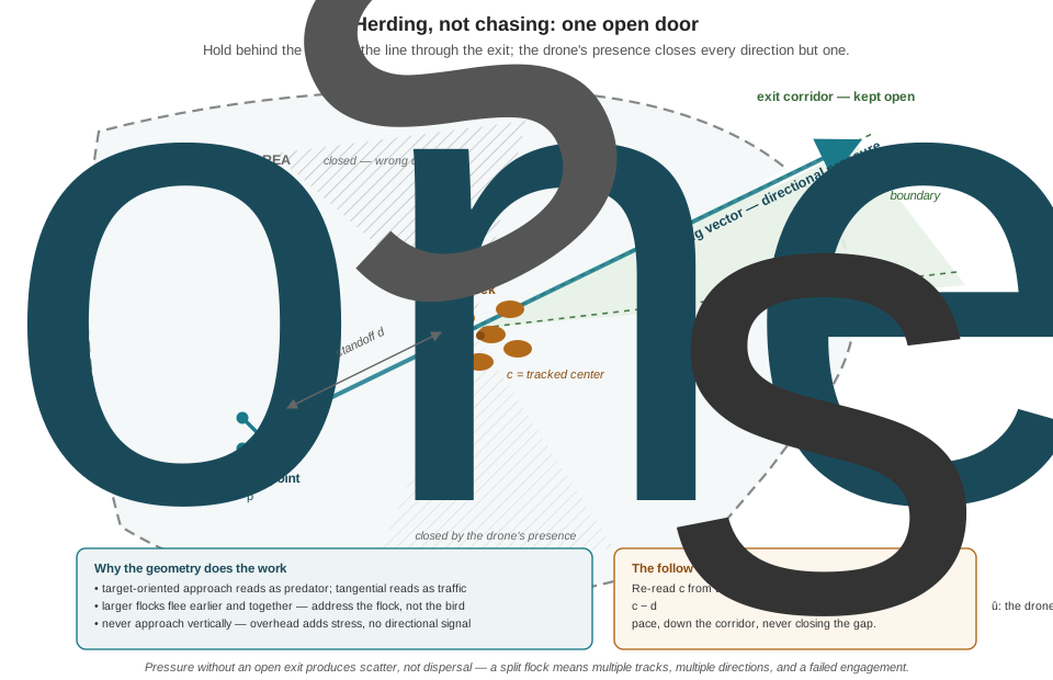
Put the three together and the herding architecture assembles itself, drawn in Figure 23.1: position the drone behind the flock relative to the desired exit, hold a standoff distance on the line through the flock toward the corridor, and let the drone’s mere target-oriented presence — not speed, not aggression — supply the directional pressure. If the exit corridor’s direction from the flock’s center \(\mathbf{c}\) is the unit vector \(\hat{\mathbf{u}}\), the drone’s hold point is simply
\[ \mathbf{p}_{\text{drone}} = \mathbf{c} - d_s\,\hat{\mathbf{u}}, \]
with \(d_s\) the standoff distance: behind the flock, on the herding vector, so that “away from the threat” and “toward the exit” are the same direction. The drone then follows the flock down the corridor at the flock’s own pace, re-evaluating \(\mathbf{c}\) from the tracker every tick. Chasing individual birds does the opposite of every line in this paragraph — it splits the flock, randomizes headings, defeats the tracker, and burns battery — which is why the herding rule is stated as the pattern family’s governing principle rather than as one option among four.
One honest addendum before the geometry hardens into confidence: pattern geometry is a strong lever, but the field evidence says it is not the only one, and possibly not the dominant one. A comparison of drone platforms hazing blackbird flocks from sunflower fields found dispersal efficacy governed by flock size and field size, not by which airframe flew (Egan et al. 2023); an industrial-site study found the multirotor outperformed the fixed-wing largely because it could fly lower and maneuver more freely — platform flexibility, not trajectory shape, was the difference (Hornain and Rosely 2024); and even hazing augmented with a chemical repellent achieved full site abandonment in only about half of trials against large flocks (Duttenhefner, Greives, and Klug 2024). A well-designed pattern earns real effect sizes, but “the right orbit radius guarantees dispersal” is not a claim the literature supports, and the running example’s metrics — displacement, return time — are there to measure what the geometry actually buys.
23.4 The Safety Radius: An Ethical Floor and an Engineering One
Every pattern in this chapter carries the same non-negotiable constraint: a minimum separation from the animals that the trajectory generator treats as a hard geometric floor. The requirement is ethical and it is engineering, and it is worth seeing that these are genuinely two arguments, not one argument told twice. Ethically, the mission’s entire license rests on the distinction between moving an animal and harming one: the objective is to guide geese out of a protected area, not to strike, exhaust, or panic them, and a trajectory that can pass through the space a startled goose might flap into has already failed that test before anything goes wrong. From the engineering side, the same floor protects the mission: a large Canada goose weighs 4–5 kg and spans up to 1.8 m of wing, and a collision at pattern speeds is a destroyed propeller, an uncontrolled descent, and a dead or injured animal — the worst outcome on every axis at once, including the public-trust axis on which all wildlife-management drone operations fly (Afridi et al. 2025). The floor also has to absorb the system’s own error budget: the flock-center estimate carries the half-metre-scale uncertainty priced in the Coordinate Frames chapter, the aircraft tracks its setpoints imperfectly in wind, and a bird can close several metres of separation in one startled second. A safety radius is the margin that lets all three of those misbehave at once without contact.
So what should the number be? Here the chapter must report an uncomfortable finding honestly: the published literature does not answer this question, and the numbers it does publish answer a different one. There is a substantial body of research on UAV–wildlife separation distances, and every part of it was written for missions trying not to disturb animals — surveys, counts, nest monitoring. That literature recommends: at least 40 m above individual waterfowl for multirotors (McEvoy, Hall, and McDonald 2016); 75 m or more above nesting snow geese (Barnas et al. 2018); roughly 100 m survey altitude and 500 m launch distance for non-disturbing goose observation (Bech-Hansen et al. 2019); and species-specific minimum approach distances of 50–170 m for colonial breeding birds, derived from measured flight-initiation distances across nearly 1,500 real drone flights (Velilla et al. 2025). The most influential best-practice paper in the field declines to endorse any universal number at all, arguing responses are too species- and context-dependent and recommending precautionary, species-specific protocols instead (Hodgson and Koh 2016).
None of those numbers can be imported into this chapter, because a deterrence mission inverts the design objective they were derived for. A survey standoff is the distance at which the animals fail to react; a deterrence standoff must be inside the flock’s flight-initiation distance, because being reacted to is the point. The 40–100 m figures are not a stricter version of this chapter’s numbers — they are the answer to the opposite question, and citing them as if they validated (or indicted) a close-range deterrence design would be exactly the decorative misuse of literature this book tries to avoid. And the question they leave open — what is the closest safe approach while deliberately provoking a flock to move? — appears to have no dedicated published safety standard at all.
The running example therefore does what an engineering project must do when the literature is silent: it chooses defaults, bounds them conservatively, and labels them as choices. The design bands used throughout this chapter — an orbit radius of 8–15 m, a swoop closest-approach horizontal separation of 5–8 m with a 3–5 m altitude floor, pattern altitudes of roughly 5–10 m — are engineering defaults: several body-lengths beyond any plausible flap-and-lunge envelope, sized to absorb the tracking error budget with margin, and consistent in spirit with the literature’s qualitative findings (geometry over speed, lateral over vertical, reaction provoked at tens of metres). They are not empirically validated thresholds, and the chapter will not pretend otherwise. What validation would look like is, usefully, already demonstrated in that same literature: the colonial-breeding-bird guidance derived its operational distances from measured FIDs over thousands of approach flights (Velilla et al. 2025) — the same method, run under deterrence conditions on the target population, is how these defaults would graduate into evidence. Until then, they are held wide, enforced hard, and logged every tick.
The enforcement, at least, is straightforward engineering. The safety radius enters the pattern generator as a constraint, not a hope: every candidate setpoint is checked against the current flock-center estimate before it is published, and any setpoint that would carry the aircraft inside the floor is projected back out along the line from the flock center. The check runs downstream of every pattern — orbit, swoop, herding — precisely so that no individual pattern’s bug can reach the animal.
23.5 A Vocabulary of Patterns
With the behavioral contract and the safety floor in place, the patterns themselves are short work — each is a small parametric trajectory family, and each exists because it occupies a distinct point on the pressure-versus-stress curve. The taxonomy has four entries: orbit, swoop, figure-8, and herding. Herding has already been drawn (Figure 23.1); it is less a trajectory than a policy — hold the moving point \(\mathbf{c} - d_s\hat{\mathbf{u}}\) and follow — and the running example treats it as the mode the others hand off to once the flock is moving the right way. The remaining three are trajectories proper.
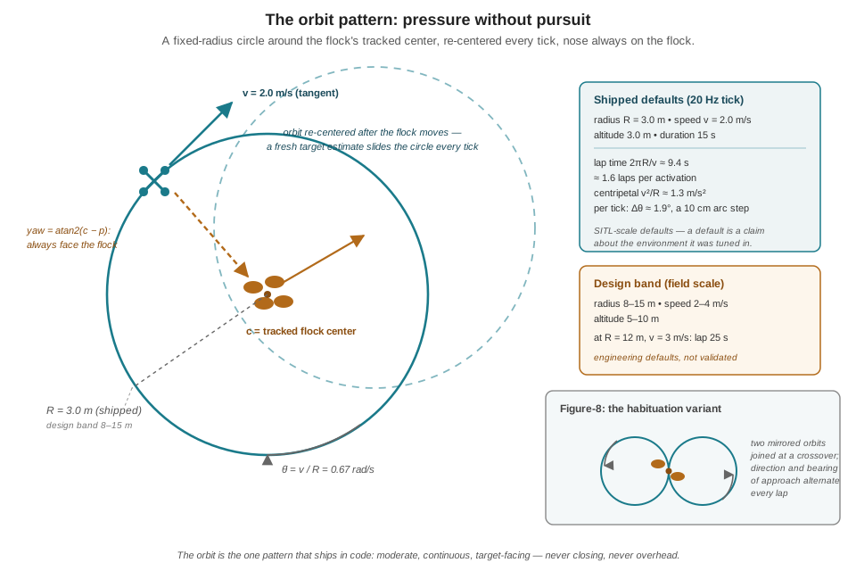
The orbit (Figure 23.2) is the workhorse and the one pattern the running example ships in code. The drone circles the flock’s tracked center at fixed radius \(R\), speed \(v\), and altitude, facing the center as it goes. As pressure it is deliberately moderate: continuous lateral presence from every bearing in turn, target-oriented enough to keep the flock’s attention, never closing, never overhead. Its parametrization is two lines of trigonometry. The drone’s position on the circle is
\[ \begin{aligned} n &= c_n + R\cos\theta \\ e &= c_e + R\sin\theta, \end{aligned} \]
and the angle advances at the angular rate that makes the linear speed come out to \(v\):
\[ \dot{\theta} = \frac{v}{R}, \]
which for the shipped defaults (\(R = 3.0\) m, \(v = 2.0\) m/s) gives \(\dot{\theta} = 0.67\) rad/s — about 38°/s, a lap every \(2\pi R / v \approx 9.4\) s, and a gentle \(v^2/R \approx 1.3\ \text{m/s}^2\) of centripetal acceleration. The critical refinement — the difference between an orbit and a decoration — is that the center \(\mathbf{c}\) is re-read from the tracker every tick, so the circle slides with the flock rather than circling the patch of grass where the flock used to be. The design-band version of the same pattern (\(R = 8\)–15 m, \(v = 2\)–4 m/s, 5–10 m altitude) trades a longer lap for a wider margin; at \(R = 12\) m and \(v = 3\) m/s the lap stretches to 25 s and the centripetal load drops below \(0.8\ \text{m/s}^2\).
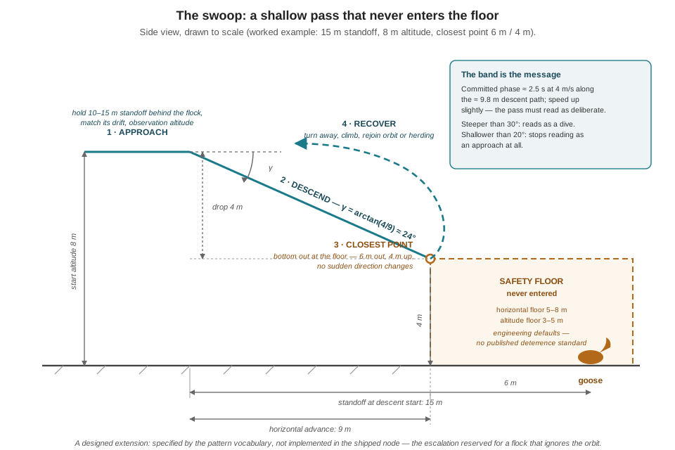
The swoop — the mission’s “buzzing pass” — is the escalation pattern, reserved for a flock that has looked at the orbit and gone back to grazing. It manufactures, briefly and under strict bounds, the one stimulus the literature says birds do not ignore: a committed, target-oriented, predator-like approach (Mulero-Pázmány et al. 2017; Storms et al. 2022). Its geometry (Figure 23.3) is a phase sequence rather than a closed curve: approach — hold a 10–15 m standoff behind the flock at observation altitude, matching the flock’s drift; descend — advance toward the flock along a shallow 20–30° glide slope, speed up slightly so the approach reads as deliberate; closest point — bottom out at the safety floor, no closer than 5–8 m horizontal separation and 3–5 m altitude, with no sudden direction changes; recover — turn away, climb back to observation altitude, and rejoin the orbit or the herding hold. The angle band is doing real work. Fixing the closest point at 6 m separation and 4 m altitude and starting the descent from a 15 m standoff at 8 m altitude gives a horizontal advance of 9 m against a 4 m drop:
\[ \gamma = \arctan\!\left(\frac{8 - 4}{15 - 6}\right) = \arctan\!\left(\frac{4}{9}\right) \approx 24^{\circ}, \]
squarely inside the band — a pass the flock sees coming from tens of metres out, shallow enough to stay unmistakably lateral rather than tipping toward the overhead geometry that maximizes stress without adding directional pressure (Vas et al. 2015). At 4 m/s along the roughly 9.8 m descent path, the entire committed phase lasts about 2.5 s. Steepen the slope past 30° and the pass starts to read as a dive; shallow it below 20° and it stops reading as an approach at all.
The figure-8 earns its place for a reason the next section makes precise: habituation. It is two mirrored orbits joined at a crossover (the inset of Figure 23.2 shows the geometry, which is why it gets no separate figure — it is the orbit, doubled and alternating), so the drone’s direction of travel and bearing of approach change every lap instead of never. Same radius mathematics, same safety floor, same re-centering; what it adds is variety, and for large flocks, coverage — the lobes can straddle a flock too wide for one circle to pressure evenly.
The four patterns compose through a simple selection policy, which the running example states as a heuristic rather than dressing it up as an algorithm: orbit a stationary flock; swoop a flock that ignores the orbit; herd a flock that is moving, to steer it down the corridor; rotate in the figure-8 when engagements repeat. A rule-based selector reading the tracker’s flock state (stationary, moving, direction) covers all four cases in a dozen lines, and sits exactly where fly_pattern() lives in the mission machine — inside HARASS_TARGET, below the FSM, above the trajectory math. Readers who notice that this selector is itself a little state machine nested inside a state are seeing the hierarchical-composition pattern the Finite State Machines chapter promised would recur.
23.6 Habituation: Why One Pattern Is Not Enough
A deterrent that works in week one and is ignored by week four has not solved the problem; it has taught the local geese a new fact about the world. Habituation — response decay to a stimulus that repeated exposure reveals as harmless — is the documented failure mode of the entire static-deterrent industry: propane cannons, scarecrows, and repeated playback all decline with exposure, a pattern reported across taxa from birds to bears to fish (Feder and Wagner 2025). A recent controlled field trial makes the contrast case cleanly: elk and deer habituated to stationary audio deterrents within a six-week deployment — and habituated more slowly when the stimulus varied, with flashing lights layered onto the audio (Rutherford, St. Clair, and Visscher 2025). The mitigation half of the claim has direct experimental support too: in a repellent study built specifically around this question, cycling the stimulus intensity fully prevented the response decline that constant exposure produced (Feder and Wagner 2025).
For drones specifically, the strongest single data point in the literature points the encouraging way. The RobotFalcon — a peregrine-shaped drone flown in predator-like pursuit of corvid, gull, starling, and lapwing flocks — cleared half its treated fields within 70 seconds, kept most fields bird-free at five minutes (against roughly 15% for untreated controls), and for several species produced return times of three to four hours where the airbase’s distress-call broadcasts bought one or two (corvids, characteristically unimpressed, returned within the hour under both); and across three months of repeated deployment it showed no evidence of habituation at all, with flight-initiation distances holding constant while static deterrents nearby were being ignored (Storms et al. 2022). The authors’ interpretation is the ethological principle this section runs on: animals cannot afford to habituate to a genuine predator, because a predator is variable, responsive, and occasionally lethal — whereas a perfectly repetitive stimulus is safe to tune out precisely because its repetition proves it harmless. A deterrent drone borrows that protection to the degree that it behaves like the former: varied approach bearings, varied patterns, movement that responds to what the flock does.
The honest boundary of the evidence: no published study has tested an orbit-versus-swoop-versus-figure-8 rotation as such, and the ordinary multirotor in the RobotFalcon study — shaped like nothing alive — still worked, just more slowly. What the literature supports is the design principle, not the specific schedule: variation and animacy delay or prevent habituation; repetition invites it. Hence the selection policy above, the figure-8’s existence, and one more running-example rule that costs nothing: never open consecutive engagements from the same bearing.
23.7 The Orbit That Actually Flies
The running example’s harassment node — harassment_node.py in the mission stack — implements the orbit pattern and nothing else, and this section reads it closely, because its structure answers three questions earlier chapters left open: how HARASS_TARGET’s “fly the deterrence pattern” actually issues setpoints, how the pattern coexists with other nodes that also want to command the aircraft, and where the “target dispersed” half of the exit guard comes from. The node’s logic, lightly condensed:
class HarassmentNode(Node):
    """Circular deterrence orbit around the tracked target.
    Publishes Offboard setpoints only while it holds the
    active-controller token; reports completion on T_HARASS_DONE."""

    def __init__(self):
        super().__init__("harassment_node")
        self.R     = self.declare_parameter("orbit_radius_m",   3.0).value
        self.speed = self.declare_parameter("orbit_speed_ms",   2.0).value
        self.hold  = self.declare_parameter("orbit_duration_s", 15.0).value
        self.alt   = self.declare_parameter("orbit_altitude_m", 3.0).value
        rate_hz    = self.declare_parameter("rate_hz",          20.0).value
        self.dt = 1.0 / rate_hz
        self.active = False          # do we own the aircraft right now?
        self.start_time = None
        self.done_sent = False
        self.center = None           # orbit center: goose (n, e)
        self.angle = 0.0
        self.create_timer(self.dt, self._tick)

    def _on_controller(self, msg):   # T_ACTIVE_CONTROLLER (String)
        self.active = (msg.data == "harassment")
        if self.active:
            self._begin()
        else:                        # token moved on: reset for next time
            self.start_time = None
            self.done_sent = False

    def _begin(self):
        if self.target is not None and self.pos is not None:
            self.center = (self.target.n, self.target.e)
            # start the orbit from wherever the drone already is:
            self.angle = atan2(self.pos.e - self.center[1],
                               self.pos.n - self.center[0])
        else:                        # no target yet: orbit in place
            self.center = (self.pos.n, self.pos.e)
            self.angle = 0.0
        self.start_time = self.now()

    def _tick(self):
        if not self.active or self.start_time is None:
            return                   # not our aircraft: publish nothing

        if self.fresh_target():      # re-center on the moving goose
            self.center = (self.target.n, self.target.e)

        # advance along the circle: linear speed -> angular rate
        self.angle += (self.speed / max(self.R, 0.5)) * self.dt
        n = self.center[0] + self.R * cos(self.angle)
        e = self.center[1] + self.R * sin(self.angle)
        yaw = atan2(self.center[1] - e, self.center[0] - n)  # face the goose

        self.pub_offboard_mode(position=True)     # every tick, or PX4
        self.pub_setpoint([n, e, -self.alt], yaw)  # drops out of Offboard

        if self.now() - self.start_time >= self.hold:
            if not self.done_sent:
                self.get_logger().info("harassment COMPLETE")
                self.done_sent = True
            self.pub_done(True)      # T_HARASS_DONE — and keep orbiting
Nearly every line is a disciplined answer to a question earlier chapters raised. The active-controller token is the distributed twin of the FSM chapter’s single-writer rule: several nodes in the stack can compute Offboard setpoints, and PX4 will obediently fly whichever arrives, so the stack shares one String topic (T_ACTIVE_CONTROLLER) naming the node that currently owns the aircraft — and this node publishes nothing unless that name is "harassment". One writer of state in a single process becomes one setpoint author in a distributed one; the tick’s first line, if not self.active: return, is the whole protocol. The activation logic in _begin() carries a small geometric courtesy with real safety value: the starting angle is computed from the drone’s current bearing off the goose, so the orbit begins from wherever the aircraft already is instead of snapping toward the circle’s \(\theta = 0\) point — no lunge across the flock’s airspace at the moment of engagement. The re-centering step is the two or three lines that make the pattern a deterrent rather than a display: each tick, a fresh target estimate slides the whole circle under the moving flock. And the angle advance — self.angle += (self.speed / max(self.R, 0.5)) * self.dt — is \(\dot{\theta} = v/R\) discretized at the 20 Hz tick, with the max(R, 0.5) guard refusing to convert a carelessly tiny radius parameter into an absurd angular rate. At the defaults, each tick advances the orbit \(0.667 \times 0.05 = 0.033\) rad — about 1.9°, a 10 cm arc step — and PX4’s position controller smooths the 20 Hz breadcrumb trail into a circle. The yaw setpoint, \(\operatorname{atan2}(\mathbf{c} - \mathbf{p})\), points the nose (and the camera) at the orbit center every tick — geometry standing in for aim, a choice the next section interrogates.
Two mismatches between this code and this chapter’s own design bands deserve to be flagged rather than smoothed over. First, the shipped default radius is 3.0 m at 3.0 m altitude — inside the 8–15 m orbit band and 5–10 m altitude band the safety discussion recommended. The defaults are sized for the SITL world the node was validated in, where the “goose” is a simulation asset and the error budget is benign; a field deployment inherits the parameters as ROS 2 parameters precisely so that the deployed configuration can live in the design band without touching code. The gap is a reminder with general force: a tunable safety parameter’s default is a claim about the environment it was tuned in. Second, the node’s completion logic is time, not behavior: after orbit_duration_s (15 s — about a lap and a half) it declares the deterrence done. Which brings up the last and most architectural detail.
The node does not stop itself. After the duration elapses it latches a log line, then publishes True on the “Harass Done” topic — T_HARASS_DONE — every tick, while continuing to orbit. This looks odd until it is read against the FSM chapter, at which point it is exactly right. State transitions belong to the mission supervisor’s tick and nowhere else; a behavior node that unilaterally stopped flying would leave the aircraft commanded by no one — the distributed version of writing self.state from a callback. Instead the node reports and keeps flying, and the supervisor closes the loop: it reads T_HARASS_DONE as the “target dispersed” half of HARASS_TARGET’s documented exit guard — target dispersed or track lost — alongside the 3 s track-loss dwell it already owns, and on either condition it commands the transition back to SEARCH_GRID and reassigns the active-controller token, which resets this node for the next engagement. The honest caveat completes the picture: T_HARASS_DONE is a proxy. “Dispersed” here operationally means “the pattern ran its designed duration,” not “the flock verifiably left” — a behavior-based test would compare the tracker’s flock position against the protected-area boundary, and the Try It builds one. Fixed-duration exposure is a defensible v1 (it bounds per-engagement stress by construction, which the ethical framing wants anyway), but the reader should know which claim the topic actually makes.
23.8 Aim, Meet Pattern
The previous chapter left a three-line stub inside HARASS_TARGET: centering_command() computes a yaw rate and vertical rate from pixel error, and fly_pattern(yaw_rate, vert_rate) was deferred here. The shipped node, note, uses neither — its yaw is \(\operatorname{atan2}\) toward the last known flock center, pure geometry, no pixels. So which is right? Both, in different roles, and the composition is worth spelling out because it is a miniature of the two-loop argument.
The geometric yaw is feedforward: it aims the camera where the target estimate says the goose is, and during an orbit it does the heavy rotational work — at the shipped defaults the nose must slew a continuous 38°/s just to keep facing the center, a rate the position-plus-yaw setpoint stream commands for free and that the centering loop would otherwise have to earn from accumulated pixel error. But feedforward is only as honest as its data. The orbit’s re-centering step consumes fresh target estimates; the estimates come from detections; and detections require the goose in frame while the aircraft flies a circle around it — the exact scenario the previous chapter’s inner loop exists for. If the goose walks two metres between target updates, the geometric yaw faces where it was, the bounding box drifts off-center, and without correction the drift compounds: fewer detections, staler center, worse aim, until the track dies and the dwell guard ends the engagement for the wrong reason. The centering loop’s yaw channel is the feedback trim that closes this hole — a small correction on top of the geometric aim, driven by where the goose actually sits in the image:
def fly_pattern(self, aim_yaw_rate, _aim_vert_rate):
    """HARASS_TARGET's action: orbit position from geometry,
    yaw = geometric feedforward + centering-loop trim."""
    n, e, yaw_ff = self.orbit_step(self.track.ned_estimate, self.dt)
    self.yaw_trim += aim_yaw_rate * self.dt          # integrate rate -> angle
    self.yaw_trim = clamp(self.yaw_trim, -0.35, 0.35)  # ~±20° of authority
    self.publish_position_setpoint(n, e, -PATTERN_ALT,
                                   yaw=yaw_ff + self.yaw_trim)
The trim integrates the centering law’s yaw-rate output into a bounded yaw-angle offset — ±20° of authority, enough to hold a walking goose in frame between target updates, too little to let a bad detection (an ID switch to a second goose, a gull) wrench the aircraft off its pattern. And the vertical channel — the second output of centering_command() — is deliberately dropped, which is why the parameter wears an underscore. Inside a deterrent pattern, altitude belongs to the pattern: the orbit holds its altitude band and the swoop flies a designed profile whose floor is a safety constraint, and no pixel error is entitled to override either. The centering loop’s vertical channel was built for free tracking, where nothing else claimed the axis; here something does, and the composition rule is the general one — feedback trims only the axes the trajectory has not already promised to safety. What survives of the previous chapter’s work is, in the end, its most important part: not the vertical channel, not even the yaw trim, but the guarantee underneath the re-centering step — that the detection stream the orbit’s geometry feeds on does not go dark the moment the aircraft starts maneuvering.
23.9 Check Your Understanding
- The shipped orbit runs at \(R = 3.0\) m and \(v = 2.0\) m/s for 15 s. Compute the angular rate, the lap time, the number of laps per engagement, and the per-tick angle step at 20 Hz. Then redo the first two numbers for a field configuration at \(R = 12\) m, \(v = 3\) m/s, and state one behavioral and one safety consequence of the larger radius.
Shipped: \(\dot{\theta} = v/R = 2.0/3.0 = 0.667\) rad/s (≈ 38°/s); lap time \(2\pi R/v = 2\pi(3)/2 \approx 9.4\) s; \(15/9.4 \approx 1.6\) laps per engagement; per tick, \(\Delta\theta = 0.667 \times 0.05 = 0.033\) rad ≈ 1.9°. Field: \(\dot{\theta} = 3/12 = 0.25\) rad/s; lap time \(2\pi(12)/3 \approx 25\) s. Behaviorally, the wider, slower orbit presents a milder stimulus — presence from every bearing but at lower angular rate, appropriate as the opening pressure level before any escalation. For safety, the 12 m radius quadruples the margin between the trajectory and the flock, so the same half-metre-scale target-estimate error and wind-tracking error consume a far smaller fraction of the separation — the error budget’s share of the standoff shrinks from roughly a fifth of 3 m to a few percent of 12 m.
- A reviewer objects: “Published research says drones should stay 40–100 m from waterfowl; your swoop bottoms out 6 m away. Your design contradicts the literature.” Write the two-part response this chapter equips you to give — first why the objection misreads the literature, then what an actually valid empirical defense of the 6 m figure would require.
First: the 40–100+ m figures come from survey and monitoring research whose design objective is avoiding behavioral response — they are measured “distance at which animals do not react” values (McEvoy, Hall, and McDonald 2016; Barnas et al. 2018; Bech-Hansen et al. 2019; Velilla et al. 2025). A deterrence mission must operate inside the flight-initiation distance, because provoking a (controlled) response is its purpose; the survey numbers answer the opposite question and neither validate nor indict a close-range design. Second: the honest status of the 5–8 m floor is an engineering default — no published standard exists for closest safe approach while deliberately provoking movement. A valid defense would replicate the FID-derivation methodology used for colonial breeding birds (Velilla et al. 2025) under deterrence conditions: instrumented approach trials on the target population, measured response and stress proxies versus separation, and a floor derived from those measurements with margin — data, not defaults.
- A swoop is planned with the closest point at 6 m horizontal separation and 4 m altitude, starting the descent from a hold at 12 m standoff and 9 m altitude. Check the approach angle against the 20–30° band; if it fails, compute the minimum standoff that fixes it while keeping the same start altitude and closest point.
Horizontal advance \(= 12 - 6 = 6\) m; drop \(= 9 - 4 = 5\) m; \(\gamma = \arctan(5/6) \approx 39.8°\) — well above the band, a pass that reads as a dive. To bring \(\gamma\) down to 30° with the same 5 m drop, the horizontal advance must satisfy \(\tan 30° = 5/d\), so \(d = 5/\tan 30° \approx 8.66\) m, requiring a standoff of at least \(6 + 8.66 \approx 14.7\) m — the design’s 10–15 m approach-hold band exists precisely so the geometry can start far enough back. (Alternatively, lower the start altitude; but starting lower spends the altitude margin that the recovery climb-out and the safety floor both depend on.)
- The RobotFalcon showed no habituation across three months of deployments, while nearby static deterrents were being ignored (Storms et al. 2022). State the ethological principle the authors invoke, the design rule this chapter derives from it, and the honest limit of what the evidence establishes about this chapter’s specific pattern rotation.
Principle: animals cannot afford to habituate to a genuine predator — predators are variable, responsive, and occasionally lethal — whereas a perfectly repetitive stimulus proves its own harmlessness through repetition, making it safe to tune out. Design rule: make the deterrent behave animate and unpredictable — vary the pattern (orbit/swoop/figure-8/herding rotation), vary approach bearings between engagements, and respond to what the flock does rather than replaying a fixed script; supporting evidence shows stimulus variation preventing or slowing response decline in other taxa (Feder and Wagner 2025; Rutherford, St. Clair, and Visscher 2025). Limit: no study has tested an orbit-versus-swoop rotation as such — the literature validates the principle (variation and animacy resist habituation), not this specific schedule, and even a non-predator-shaped multirotor deterred flocks, just less effectively than the falcon mimic.
- After 15 s the harassment node latches “COMPLETE,” publishes
TrueonT_HARASS_DONEevery tick — and keeps orbiting. Explain why not stopping is correct architecture rather than an oversight, how the supervisor turns this topic into the FSM’s documented “target dispersed or track lost” exit, and what claimT_HARASS_DONEactually makes versus the claim its name suggests.
Transitions belong to the mission supervisor’s tick — the single writer of state. If the node stopped publishing setpoints on its own, the aircraft would be momentarily commanded by no one, and the decision “harassment is over” would have been made outside the one place all such decisions are made and logged. So the node reports (T_HARASS_DONE) and keeps flying until authority is taken from it: the supervisor reads the topic as the “dispersed” half of the exit guard (the 3 s track-loss dwell supplies the other half), commands HARASS_TARGET → SEARCH_GRID, and reassigns the active-controller token, whose change resets the node. The claim the topic actually makes is “the pattern ran its designed duration” — a time-based proxy that bounds per-engagement stress but does not verify the flock left; a behavior-based version would test the tracked flock position against the protected-area boundary before asserting dispersal.
- In the composed
fly_pattern(), the centering loop’s yaw output survives as a clamped trim while its vertical output is discarded entirely. Justify both decisions, and describe the failure cascade that unfolds if the trim is removed and the goose walks steadily while the drone orbits.
Yaw survives because aim is a job nothing else owns: the geometric yaw is feedforward from the last target estimate, and the pixel-error trim corrects for everything that happens between estimates (goose motion, estimate error, attitude transients), keeping detections flowing. It is clamped (±20°) so a corrupted detection can bend the aim but never wrench the aircraft off its pattern. The vertical channel is discarded because inside a pattern altitude is already claimed — by the orbit’s altitude band and, in the swoop, by a safety-critical floor — and no pixel error may override a safety constraint: feedback trims only axes the trajectory hasn’t promised elsewhere. Without the trim: the goose walks, the geometric yaw faces its old position, the bounding box drifts toward the frame edge, detections become intermittent, so target updates slow, so re-centering staleness grows, so the aim worsens — a compounding loop that ends with the track silent, the 3 s dwell expiring, and the engagement terminated by track loss while the goose is still standing in the protected area.
23.10 Try It
Part 1 — fly the shipped orbit and hold it to its numbers. Implement the harassment node’s orbit logic in SITL against a scripted goose, wired under the mission machine from the Finite State Machines chapter with the active-controller token and T_HARASS_DONE in place of the old stub. Start with the shipped defaults (\(R = 3\) m, \(v = 2\) m/s, 15 s, 20 Hz). First, the acceptance metric: log commanded versus actual position at full rate and compute the average tracking error over the engagement — the design target is under 1 m average error, and a clean SITL orbit should beat it comfortably; if it doesn’t, check whether your per-tick angle step is being published at the rate you think (a 10 Hz timer flying a 20 Hz parameterization orbits at half speed and double lap time — the logs make this instantly visible). Second, re-centering: script the goose to walk at 1 m/s mid-engagement and confirm the orbit’s center track follows with bounded lag while tracking error stays in budget. Third, the exit paths: let one engagement run to completion and verify the supervisor — not the node — performs the transition on T_HARASS_DONE with a [STATE CHANGE] line naming the reason; then kill the target stream mid-orbit and confirm the node keeps circling the stale center until the 3 s dwell, not anything in the pattern code, ends the run. Finally, promote the proxy: add a boundary test that compares the tracked goose position against the protected-area polygon (the point-in-polygon machinery from the Geofencing chapter, pointed at the goose instead of the drone) and publish a behavior-based done signal alongside the timed one; log how often, in your scripted scenarios, the two disagree.
Part 2 — build the swoop and prove its floors. Extend the node with the swoop as a four-phase machine — APPROACH, DESCEND, CLOSEST, RECOVER — parameterized by standoff, start altitude, closest-point separation and altitude, and speed. Before flying it, compute the approach angle from your chosen parameters and assert in code that it lands in the 20–30° band (Check 3 is the arithmetic); at runtime, log horizontal separation and altitude against the safety floor every tick and treat any violation as a test failure, not a warning — the floor is the specification. Fly it in SITL against both a stationary and a drifting goose, and verify the recovery phase returns the aircraft to observation altitude and re-enters the orbit cleanly. Then compose an engagement the way the selection policy prescribes: orbit, escalate to one swoop when the scripted goose ignores it, return to orbit, and end via T_HARASS_DONE — confirming the pattern switches happen inside HARASS_TARGET (the nested machine) while the mission-level FSM sees one continuous state. If you have the previous chapter’s synthetic-detection rig, add the aim trim from fly_pattern() and re-run the walking-goose scenario with the trim enabled and disabled; the disabled run’s detection-dropout curve is this chapter’s whole argument for the inner loop, drawn by your own logs.
Related Lab: See Appendix B for the lab assignment that applies this chapter’s concepts.
The pattern library closes the loop the FSM opened: the mission can now search, find, confirm, engage, deter, and resume — one aircraft, one flock, one corridor. The seams that remain are the honest kind. The safety floors are defaults awaiting field-derived numbers; the dispersal signal is a timer awaiting a boundary test; and the deeper question — what repeated, automated disturbance does to a population over a season, and when running this system is the right call at all — is held open deliberately for the Ethics and Ecology of Autonomous Wildlife Management chapter. And one scaling seam is visible from here: a single drone herds a single cohesive flock well, but the moment a flock splits — or a second flock lands across the site — one aircraft cannot hold two herding vectors at once. Pressure from multiple bearings simultaneously, sectors of a protected area worked in parallel, roles assigned and reassigned as flocks merge and split: that is coordination, not trajectory design, and it is where the Multi-Agent Systems and Coordination chapter picks up next.